5 cp10 double flushed mechanical seal removal – Viking Pump TSM285: Classic+ Lobe Pump User Manual
Page 26
SECTION TSM 285
ISSUE
A
PAGE 26 OF 36
- Install lipseals (7.08) and O-rings (7.07) to housing(s)
(7.06).
- Install housing(s) (7.06) to shafts (5.01 and 5.02).
- Install rotary seal cartridges (7.05) to shafts (5.01 and 5.02)
positioning to correct setting distance, see Figure 50 and
tightening screws in rotary seal cartridge assemblies (7.05)
to correct torque, refer to section 8.2.
Note: Access to screws in rotary cartridge seal assemblies
(7.05) is through the flush pipe connections of housing
(7.06).
- Install casing (3.01), O-rings (2.04), rotors (2.01), O-rings
(2.03), rotor retainers (2.02) and head (1.01), refer to sections
4.1.4 (CP10, CP20 and CP30) or 4.2.5 (CP40).
- Secure housing(s) (7.06) to casing (3.01) with screws (7.10)
ensuring correct location onto dowels (7.09).
5.2.5 CP10 DOUbLE fLUSHED
MECHANICAL SEAL REMOVAL
Refer to Figure 52.
5.2.3 CP10, CP20, CP30 AND CP40
SINGLE fLUSHED
MECHANICAL SEAL REMOVAL
Refer to Figure 51 for CP10, CP20, CP30 and CP40
- Remove head (1.01), rotor retainers’ (2.02), O-rings (2.03),
rotors (2.01), O-rings (2.04) and casing (3.01), refer to
sections 4.1.2.1 and 4.1.2 (CP10, CP20 or CP30) or 4.2.2.1
(CP40).
- Loosen but do not remove screws in rotary seal cartridge
assemblies (7.05), which secure rotary seal cartridges to
shafts (5.01 and 5.02).
Note: Access to screws in rotary seal cartridge (7.05) is
through the flush pipe connections of housing (7.06).
- Remove rotary seal cartridges (7.05) with O-ring (7.02) from
shafts (5.01 and 5.02).
- Remove housing(s) (7.06) complete with lipseals (7.08) and
O-Ring(s) (7.07) from shafts (5.01 and 5.02).
- Remove lipseals (7.08) and O-ring (s) (7.07) from housing(s)
(7.06).
- Remove stationary seal seats (7.04) and O-rings (7.01) from
casing (3.01).
5.2.4 CP10, CP20, CP30 AND CP40
SINGLE fLUSHED
MECHANICAL SEAL
REPLACEMENT
Refer to Figure 51 for CP10, CP20, CP30 and CP40
- Install O-rings (7.01) to stationary seal seats (7.04).
- Install stationary seal seats (7.04) to casing (3.01) ensuring
correct location of O-rings (7.01).
Note: On CP10 models the stationary seal
seat (7.04) has a location recess which fits
over the anti-rotation washer (7.13).
Note: On CP20, CP30 and CP40 models the
stationary seal seat (7.04) has a triangular
shape, which must locate fully into the casing
(3.01) bore.
- Remove head (1.01), rotor retainers’ (2.02), O-rings (2.03),
rotors (2.01), O-rings (2.04) and casing (3.01), refer to
sections 4.1.1 and 4.1.2.
- Loosen but do not remove screws (7.11), which secure rotary
seal cartridge assemblies (7.11) to shafts (5.01 and 5.02).
Note: Access to screws (7.13) is through the flush pipe
connections of housing (7.06)
- Remove rotary seal cartridges (7.11) with O-rings (7.02) from
shafts (5.01 and 5.02).
- Remove housing (7.06) complete with O-ring (7.07),
stationary seal seats (7.12) and O-rings (7.01) from shafts
(5.01 and 5.02).
- Remove stationary seal seats (7.12), O-rings (7.01) and O-
ring (7.07) from housing (7.06).
- Remove stationary seal seats (7.04) and O-rings (7.01) from
casing (3.01).
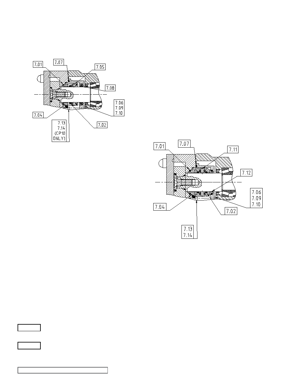
figure 52
Double flushed Mechanical Seal
figure 51
Single flushed Mechanical Seal
WARNING
WARNING