Viking Pump TSM285: Classic+ Lobe Pump User Manual
Page 11
SECTION TSM 285
ISSUE
A
PAGE 11 OF 36
Note: Care should be taken not to exceed the
lower of either the pump’s maximum pressure
rating or the system design pressure.
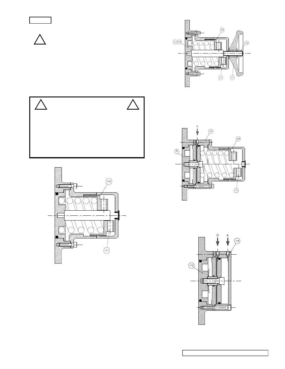
- To use the air lift system, the regulated air
supply must be routed through a change-over
valve in order to transfer air from the relief valve
load air chamber, connection ‘A’, to the lift air
chamber, connection ‘B’, while depressurizing
the load chamber and vice versa. The change-
over valve will actuate the air lift which will lift
when the air supply is diverted to connection
‘B’, and will close, restoring normal relief valve
operation, when the air supply is diverted back
to connection ‘A’.
figure 11
Spring Loaded Integral Pressure Relief Valve
CP10, CP20, CP30, CP40
figure 12
Spring Loaded Integral Pressure Relief Valve
with Manual Lift
CP10, CP20 and CP30
figure 13
Spring Loaded Integral Pressure Relief Valve with Air Lift
CP10, CP20 and CP30
figure 14
Air Loaded Integral Pressure Relief Valve with Air Lift
CP10, CP20, CP30 and CP40
DANGER !
Under no circumstances should any
attempt be made to dismantle a pressure
relief valve which has not had the spring
pressure relieved, is still connected to a
pressurized air supply, or is mounted on a
pump that is operating. Serious personal
injury or pump damage may occur.
!
!
!
WARNING