5 cp50 casing, rotor and head assembly – Viking Pump TSM285: Classic+ Lobe Pump User Manual
Page 24
SECTION TSM 285
ISSUE
A
PAGE 24 OF 36
- Be sure faces of spacers’ (5.24) are parallel after
machining.
- After any machining of spacers’ (5.24), check front clearances
for both rotors, refer to section 8.1, Clearance Chart.
- Install spacers (5.24) to shafts (5.01 and 5.02) ensuring they
are correctly located.
- Install pins (5.23) to shafts (5.01 and 5.02) using a liquid
retainer (Loctite 648 or similar).
- Install product seals; refer to section 5.3 and 6.3.
- Install casing (3.01) to gearbox (4.01) locating onto dowels
(4.03) and securing with dome nuts (4.08) tightened to
correct torque, refer to section 8.2.
- Install O-rings (2.05) and rotors (2.01) to shafts (5.01 and
5.02).
- Lubricate retainers’ (53) with oil and install to shafts (5.01
and 5.02).
- Clamp one rotor (2.01) to shaft (5.01 or 5.02) using tool and
associated stud and nut, see Figure 48, ensuring that two
of the screws in retainer (2.05) are visible through holes in
tool.
- Moderately tighten visible screws in retainer (2.05) in clamped
rotor to lock rotor in position. Remove tool and associated
stud and nut, tighten fully screws in retainer (2.05) to correct
torque, refer to section 8.2, taking note of typical tightening
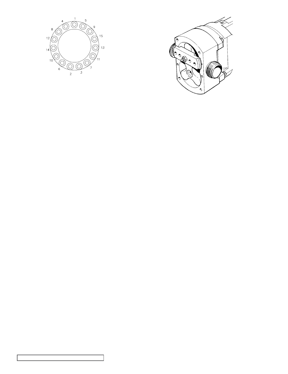
sequence, see Figure 47.
- Repeat clamping and retainer (2.05) tightening procedure for
other rotor.
- Remove tool and associated stud and nut.
- Install O-rings (2.03) and retainers (2.02) tightening to correct
torque refer to section 8.2, using tool.
- Check all rotor clearances, front, rear, top/bottom, sides’ and
mesh, refer to section 8.1, Clearance Chart.
- Install head (1.01) with O-ring (1.02) and secure with nuts
(1.03) tightened to correct torque, refer to section 8.2.
- Install oil seal (6.03) to gearbox cover (6.00).
- Apply liquid sealant (Loctite 573 or similar) to sealing area of
gearbox cover (6.00) and install to gearbox (4.01), locating
on dowels (6.06) and securing with screws (6.11), tightened
to correct torque, refer to section 8.2.
- Install drive key (6.12).
- Install drain plugs (6.09) and breather plugs (6.10).
- Remove rotor retainers (2.02) using tool, rotors (2.01) and
spacers (5.24)
4.3.5 CP50 CASING, ROTOR AND
HEAD ASSEMbLy
Referring to Figure 33 and Figure 44.
- Install spacers’ (5.24) and product seal sleeves (7.15) to
shafts (5.01 and 5.02).
Note: Pins (5.23) should not be installed at this stage.
- Install casing (3.01) to gearbox (4.01) locating on dowels
(4.03) and secure with dome nuts (4.08) tightened to correct
torque, refer to section 8.2.
- Install rotors (2.01) to shafts (5.01 and 5.02).
- Clamp one rotor (2.01) to shaft (5.01 or 5.02) using tool and
associated stud and nut see Figure 48.
- Using a depth micrometer or similar device, measure front
clearance; refer to section 8.1, Clearance Chart, between
the casing and clamped rotors front face and check that this
corresponds to the appropriate clearance as indicated on the
Clearance Chart. Note any discrepancy in front clearance.
- Remove tool and associated stud and nut (shown above).
- Repeat clamping and front clearance measurement for other
rotor (again note any discrepancy in front clearance.
- Remove tool and associated stud and nut.
- Remove rotors (2.01), casing (3.01) and product seal sleeves
(7.15).
- If any discrepancies were noted in front clearances, between
rotors and front face of casing, then spacers (5.24) will
require machining to shorten them to achieve the correct
front clearance, refer to section 8.1.
Note: If it is found that the measured front clearance is
greater than that shown in the Clearance Chart, refer
to section 8.1, then new spacers (5.24) will need to be
obtained and machined to the correct lengths to achieve
correct front clearance.
figure 48
Rotor Clamping Tool fitment
figure 47
Retainer Tightening Sequence