Viking Pump TSM285: Classic+ Lobe Pump User Manual
Page 13
SECTION TSM 285
ISSUE
A
PAGE 13 OF 36
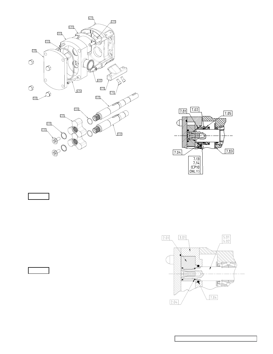
Single O-ring Seal as shown in Figure 18 – see section 6.2.1
for removal and replacement.
- Remove rotor (2.01).
- Remove O-ring seal (7.04) from casing (3.01).
Note: The socket tool should always be
used, the use of other tools may damage the
retainer.
- Remove retainer O-rings (2.03).
- Remove rotors (2.01) from shafts (5.01 and 5.02).
- Remove rotor O-rings (2.04) – Not fitted on O-ring seal
version of CP10.
Note: If the pump is fitted with O-ring Seals (instead of
mechanical seals) then the O-ring seal will now be visible
– Chapter 6.0 for further information.
4.1.2 CP10, CP20 AND CP30
CASING REMOVAL
Note: Ensure all pipe work is disconnected
before commencing casing removal.
4.1.2.1 CP10, CP20 AND CP30
CASING REMOVAL
fOR PUMPS fITTED WITH
SINGLE UN-fLUSHED
MECHANICAL SEALS AND
SINGLE O-RING SEALS
CP10 Pump Only
(After completing section 4.1.1)
- Slide casing (3.01) from bearing housing (4.01), noting
it is located on dowels (4.03), keep arch shims (4.05) in
appropriate sets if they are to be reused.
CP20 and CP30 Pump Only
(After completing section 4.1.1)
- Remove casing retention socket cap head screws (4.04)
with appropriate metric allen key (not supplied).
- Slide casing (3.01) from bearing housing (4.01), noting
it is located on dowels (4.03), keep arch shims (4.05) in
appropriate sets if they are to be reused.
Single Un-Flushed Mechanical Seal as shown in Figure 17.
- See section 5.2.1 for removal and section 5.2.2 for
replacement.
figure 17
Single Un-flushed Mechanical Seal
figure 16
CP20/CP30 Exploded View of Casing
and Rotor Assembly
figure 18
O-ring Seal
WARNING
WARNING