4 cp50 gearbox assembly – Viking Pump TSM285: Classic+ Lobe Pump User Manual
Page 23
SECTION TSM 285
ISSUE
A
PAGE 23 OF 36
- Support pump with shafts in the vertical position with rotor
end up.
- Remove screws (5.07), and then remove bearing retainers’
(5.06) and O-rings (5.21), then remove lipseals (5.03) from
bearing retainers’ (5.06).
- Remove shafts (5.01 and 5.02) from gearbox (4.01). Shafts
(5.01 and 5.02) will be complete with pins (5.23), spacers
(5.24), bearings (5.05), spacers (5.05), tab washers (5.20),
lock nuts (5.19), bearings (6.02) and spacers (6.02).
- Remove bearings (6.02) complete with spacers (6.02) from
shafts (5.01 and 5.02) keep them in matched sets and identify
position.
- Remove lock nuts (5.19) and tab washers’ (5.07).
- Remove bearings (5.05) complete with spacers (5.05) from
shafts (5.01 and 5.02), keep them in matched sets and
identify position.
- Remove shaft sleeve drive pins (5.23) from shafts (5.01 and
5.02), remove spacers (5.24), note fitting position.
4.3.4 CP50 GEARbOX ASSEMbLy
The following procedure describes the assembly of the gearbox,
refer to Figure 44.
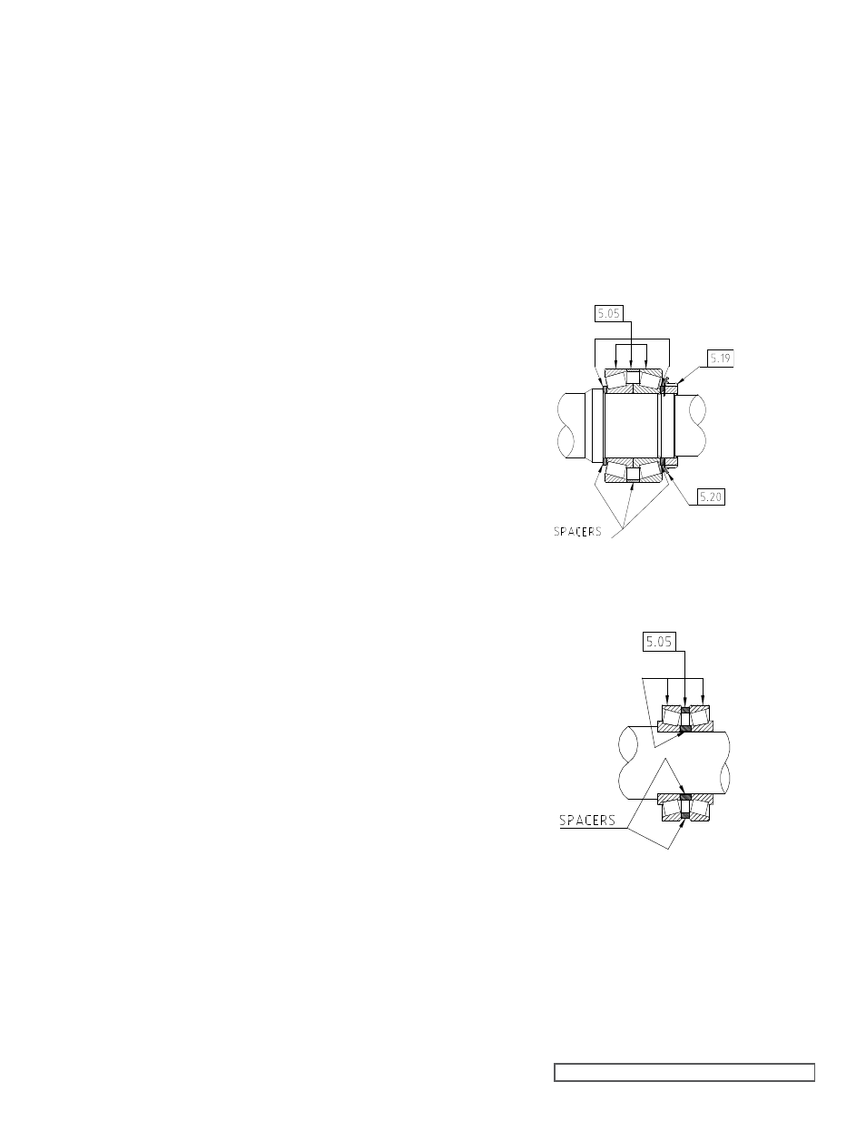
- Install bearings (5.05) complete with spacers (5.05) to
shafts (5.01 and 5.02) ensuring correct positioning of all
components as either removed in 4.3.3. Above or supplied
as new replacement set, see Figure 45.
- Install spacers (5.24), product seal sleeves (28 or 66), rotor
keys (78) and rotors (41) to shafts (5.01 and 5.02) and secure
with rotor retainers (35) using tool (58).
- Install tab washers (5.07) and lock nuts (5.19) tightening to
correct torque, refer to section 8.2. Secure tab washers.
Note: Ensure that the cups of the rear most bearings (5.05)
are in position on inner races before proceeding.
- Install bearings (6.02) complete with spacers (6.02) to
shafts (5.01 and 5.02) ensuring correct positioning of all
components as either removed in 4.3.3 above or as supplied
as new replacement set, see Figure 46.
- Support gearbox (4.01) in a vertical position and install shafts
(5.01 and 5.02) to gearbox (4.01).
- If not already installed install cups of front most bearings
(5.05).
- Install lipseals (5.03) to bearing retainers’ (5.09).
- Install retainers’ (5.09) and O-rings (5.21) and secure with
screws (5.07) tightening to correct torque, refer to section
8.2.
- Return pump to normal horizontal mounting position.
- Install lipseal (6.19) to gearbox (4.01). Install O-ring (5.22),
spacer (5.18) and key (5.10) to drive shaft (5.01).
- Install timing gears (5.09) to shafts (5.01 and 5.02).
- Install tab washer (5.11) and lock nut (5.12) tightening to
correct torque, refer to section 8.2. Secure tab washer
(5.11).
- Rotate shafts (5.01 and 5.02) such that keyways for rotor
keys are vertically upwards.
- Lubricate retainer (5.16) with oil and install to timing gear
(5.09). Do not tighten.
Note: Pins (5.23) should not be installed at this stage.
- Clamp gear (5.09) to shaft (5.02) using tool (supplied) and
associated stud and nut, ensuring that two screws in retainer
(5.16) are visible through holes in tool.
- Check rotor mesh clearance against Clearance Chart,
refer to section 8.1. Adjustment of mesh clearance is made
by rotating the shafts (5.01 and 5.02). Having achieved
optimum mesh clearance, partially tighten visible screws
in retainer (5.16), to clamp gear in place. Remove tool and
associated studs and nuts. Fully tighten screws in retainer
(5.16) to correct torque, refer to section 8.2, taking note of
typical tightening sequence, see Figure 47.
- After tightening of retainer (5.16) check rotor mesh clearance;
refer to section 8.1 (Clearance Chart).
figure 45
front bearing Assembly - CP50
figure 46
Rear bearing Assembly - CP50