2 double mechanical seal (for high pressure flush), 0 flushed product seals auxiliary services – Viking Pump TSM285: Classic+ Lobe Pump User Manual
Page 30
SECTION TSM 285
ISSUE
A
PAGE 30 OF 36
7.1 SINGLE MECHANICAL SEAL
(fOR LOW-PRESSURE
QUENCH OR fLUSH)
See Figure 17 (CP10), Figure 27 (CP20, CP30, CP40) and
Figure 50 (CP50).
Refer to section 4.3.3.
This seal arrangement requires a supply of media to the
outboard side of the mechanical seal to quench or flush the
seal area. The nature of the pumped media and the specific
duty conditions will determine whether a quench or a flush is
required.
A quench provides a static head. The quench media vessel
should be mounted a minimum of 0.5m (1.5 Feet) above
the pump, preferably directly above the seal area. The
interconnecting pipe work should be as straight as possible,
avoiding horizontal runs, and with the minimum number of
bends and restrictions.
For a suitable flush, the media must be supplied at a flow rate
of 4.5 Liters per minute per shaft seal.
Note: The limiting flush or quench pressure
in any application is 0.7 bar (10 psig).
7.2 DOUbLE MECHANICAL SEAL
(fOR HIGH PRESSURE fLUSH)
See Figure 18 (CP10) and Figure 28 (CP20, CP30, CP40) and
Figure 51 (CP50)
Refer to section 4.3.4.
This seal arrangement requires a supply of media to be
circulated between the inboard and outboard mechanical
seals.
The flush media must be supplied at a flow rate of 4.5 Liters per
minute per shaft seal assembly.
The flush pressure must be a minimum of 1 Bar (15 psi) greater
than the maximum discharge pressure created by, or the
maximum suction pressure applied to, the pump, whichever
is the greater.
Note: The limiting flush pressure in any
application is 13 bar (188 psig).
Note: The liquid supply connections to flushed seals are
made using the threaded ports on the sides of the seal
housings (two per seal, except CP10 & CP20 models,
which have common seal housings encompassing both
shaft seals). for models CP30 to CP50 inclusive, one
port on each housing should be used for flush ‘in’ and the
other for flush ‘out’. The pipe work should be arranged to
provide an independent flush to each seal.
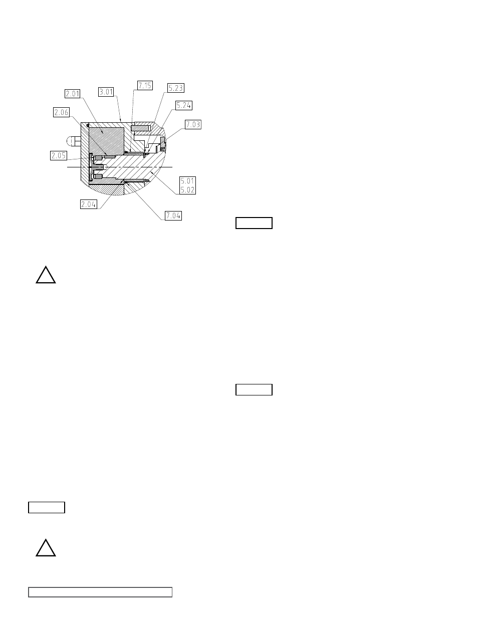
- Before assembly or disassembly of the seals,
ensure pump is fully shutdown, refer to
section 3.5.
- Install O-ring (7.04) into the casing (3.01).
- Install rotary seal sleeves (7.15) onto shafts (5.01 and 5.02),
ensuring engagement of slots in rotary seal sleeves (7.15)
and drives pins (5.230
- Install O-ring (2.04 onto shaft (5.01 and 5.02).
Note: During installing of the rotors to shafts care must
be taken not to damage or unseat the O-ring seal when
inserting the rotor (2.01) into O-ring (7.04).
- To disassemble reverse the above procedure.
7.0 fLUSHED PRODUCT SEALS
AUXILIARy SERVICES
i) Terminology.
a) “Quench”
- To provide a liquid barrier that is not induced to flow
through the seal area by any external means.
b) “Flush”
- To provide a liquid barrier that is induced to flow
through the seal area by an external means.
ii) Quench or Flush Media
The media used for quenching or flushing a seal
area must be fully compatible with the pumped
media, and the relevant materials of construction
of the pump.
Special consideration must be given to the
temperature limitations of the media to ensure
that no hazards are created, e.g. risk of fire or
explosion.
6.3 O-RING SEAL fOR CP50 PUMP
6.3.1 CP50 O-RING SEAL ASSEMbLy
AND REMOVAL
figure 58
CP50 O-ring Seal
!
WARNING
WARNING
!
WARNING