3 cp50 gearbox disassembly – Viking Pump TSM285: Classic+ Lobe Pump User Manual
Page 22
SECTION TSM 285
ISSUE
A
PAGE 22 OF 36
- Remove screws (6.11) and gearbox cover (6.00). The
gearbox cover (6.00) is located on dowels (6.06) and sealed
with suitable liquid sealant.
- Remove oil seal (6.03) from gearbox cover (6.00).
- Loosen by two full turns all screws in retainer (5.16) on the
lay shaft (5.02). Once this is done the retainer may release
its grip. If it does not become free identify and remove the
three screws which differ in color (these may also have a
washer under the head). Once these screws are removed
tapped holes will be revealed. Insert three jackscrews (M10
x 40 setscrews), into the tapped holes and tighten until the
retainer’s grip is broken. Remove the retainer.
- Remove lock nut (5.12) and tab washer (5.11), then remove
timing gears (5.09), gear key (5.10), spacer (5.18), O-ring
(5.22) and lipseal (83).
4.3.3 CP50 GEARbOX
DISASSEMbLy
(After completing 4.3.1 and 4.3.2)
Before proceeding with disassembly of the gearbox remove
product seals; refer to section 5.3 for Mechanical Seals and
6.3 for O-ring Seals.
The following procedure describes complete disassembly of
the gearbox, refer to Figure 44.
- Remove guard (4.06) and shaft slingers (7.03) if fitted.
- Remove drive key (6.12).
- Remove oil drain plugs (6.09) and breather plugs (6.10),
drain oil into suitable container and retain (inspection may
later be required).
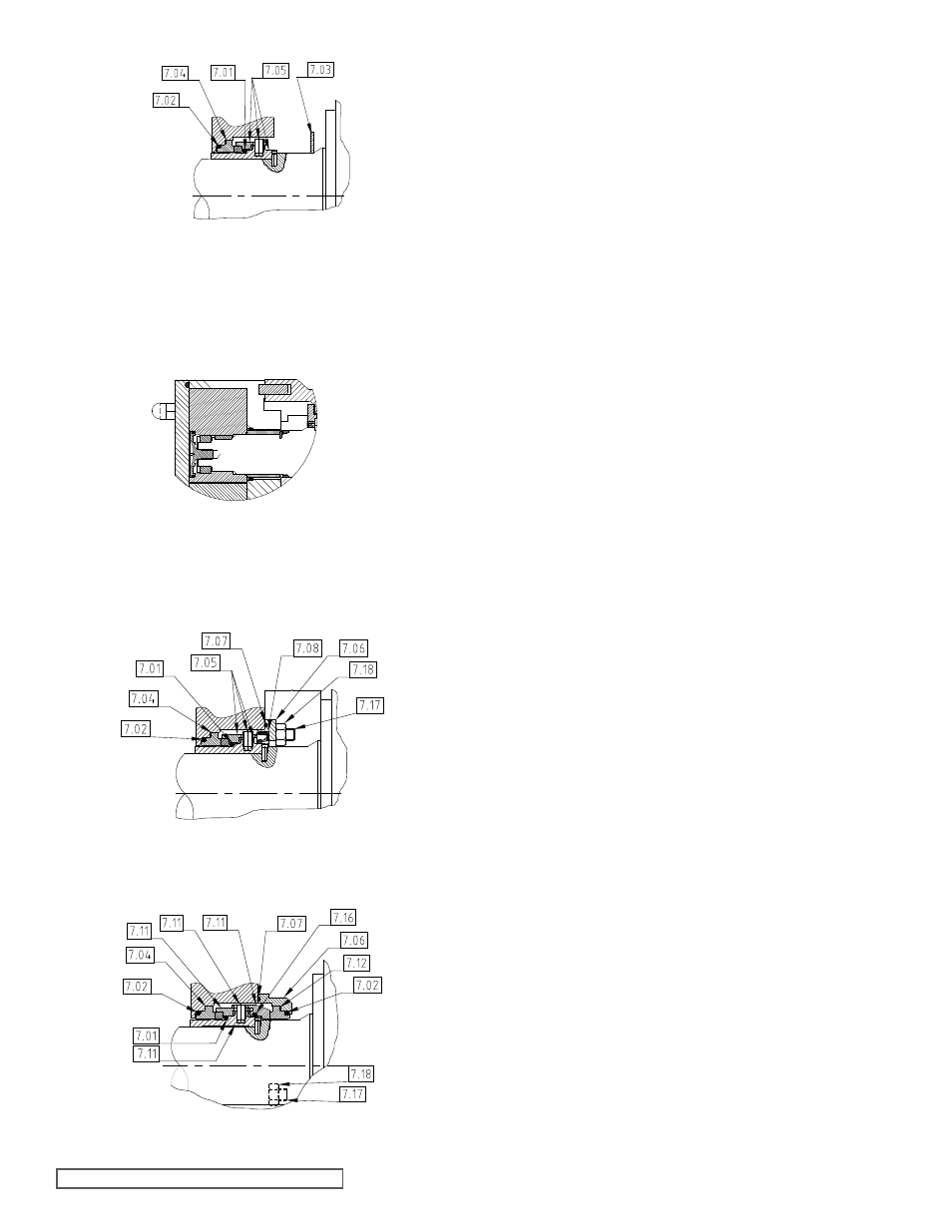
figure 42
Single flushed Mechanical Seal for CP50
figure 43
Double flushed Mechanical Seal for CP50
figure 40
Single Un-flushed Mechanical Seal – CP50
figure 41
Single O-ring Seal CP50