23 complete the installation, Complete the installation -41, Ultra-cut 400 xt – Tweco 400 XT Ultra-Cut Plasma Cutting System User Manual
Page 63
ULTRA-CUT 400 XT
Manual 0-5275
INSTALLATION
3-41
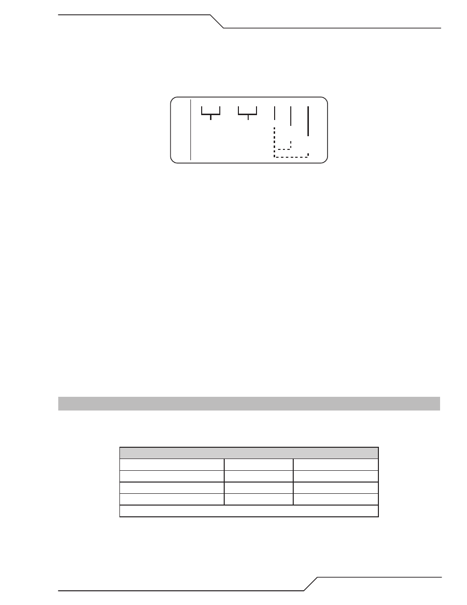
Arc Voltage Connections.
The XT plasma supplies provide a terminal strip, TB4, on the right side ahead of the CCM module for connections to Arc V- (Torch);
Tip V (Pilot); Arc V + (Work). If the V-D board requires separate power, 24 VAC and 120 VAC is available on the terminal strip
TB4. Refer to the wiring diagram in the Appendix for more information.
24 VAC
@ 1A
TB4
1
2
3
4
5
6
7
120 VAC
@ 100 ma.
Work
Tip Volts
(Pilot)
Arc Volts
(Torch)
Art # A-11954
“Ohmic” or Shield (cup) cable.
Some height controls including the iHC find the plate using an electrical or resistance measurement, thus “ohmic”, contact between
the conductive end of the torch and the metal or “plate” being cut. A wire, usually a single highly flexible wire that withstands the
reflective heat from the arc, is connected between the V-D board and the torch shield cup. The XT torch includes a metal spring
clip which slips into a groove in the shield cup allowing easy removal for parts change. The Ohmic wire can be connected to this
clip with a ¼” female push-on terminal.
Significant amounts of high frequency (HF) energy causing electromagnetic interference (EMI) can be conducted along this wire
due to it’s close coupling to the torch. This is the reason for mounting the V-D board away from the CCM and close to the rear
panel where the Ohmic wire does not need to pass near other sensitive electronics. It is especially recommended that the Ohmic
wire not be routed near the CCM module or along the torch leads.
Refer to Appendix for wiring diagram.
Ferrite cores.
It is recommended that the Ohmic Sensing wire be wrapped through a ferrite core with several turns, at least 3 but more is bet-
ter, to reduce the energy conducted to the V-D board and into the plasma supply. The ferrite core should be located on the wire
where it enters the plasma supply. A second ferrite core added several feet (couple of meters) from the torch will further reduce
the conducted EMI that may couple to other cable/wires and cause interference.
Refer to Appendix for wiring diagram.
3.23 Complete the Installation
1. Remove the cap from the coolant tank. Fill the coolant tank to the level shown, with Thermal Dynamics
coolant. The coolant level is visible through the translucent coolant tank. The amount of coolant required
varies with torch leads length.
Coolant Capabilities
Cat. Number and Mixture
Mixture
Protects To
7-3580 ‘Extra-CoolTM’
25 / 75
10° F / -12° C
7-3581 ‘Ultra-CoolTM’
50 / 50
27° F / -33° C
7-3582 ‘Extreme CoolTM’
Concentrate*
-65° F / -51° C
* For mixing with D-I CoolTM 7-3583