Ultra-cut 400 xt, 102 pilot ignition failure – Tweco 400 XT Ultra-Cut Plasma Cutting System User Manual
Page 155
ULTRA-CUT 400 XT
Manual 0-5275
APPENDIX
A-�7
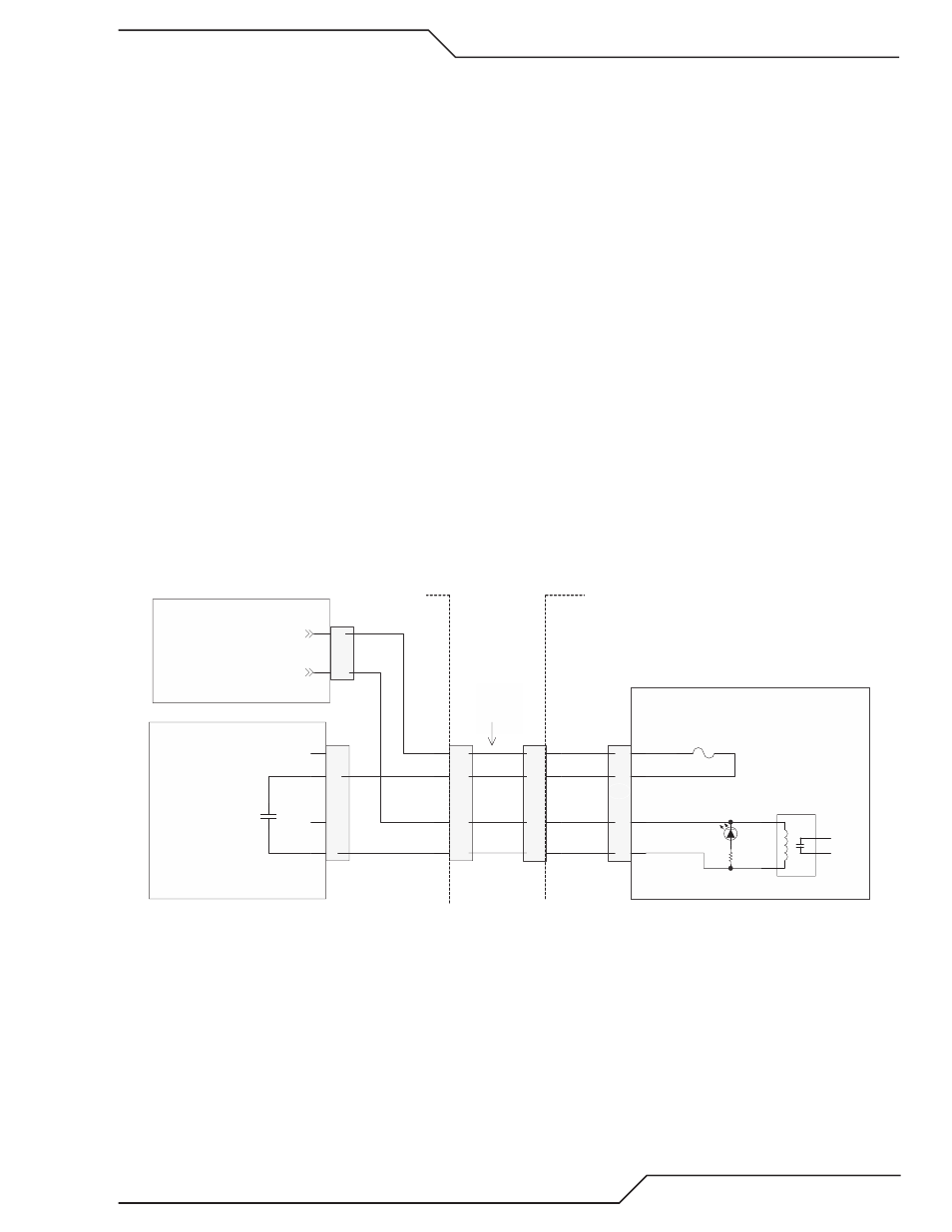
If a TSC 3000 is not connected or unit is an Auto-Cut, K7 on the Relay PCB is de-energized and GND is connected through
its normally closed contacts. If the TSC is connected, 2� VAC through a jumper in the TSC 3000 energizes K7, opening its
NC contacts and now GND connects through the TDC 3000 Plasma Enable switch. The GND obtained by either path passes
through the GCM 2010 Plasma Enable switch or through a jumper (J5�-1 to J5�-2) present in the other gas controls (GCM
1000 XT or DMC 3000) and is connected to the coil of K1 on the I/O PCB. If the CNC Plasma Enable is also active (D2 is
on) +15V will be connected to K1’s coil through the relay K7 on the I/O PCB. This energizes K1 and turns on D3, Plasma
Enable LED. The contacts of K1 go back to the Relay board and to the Gas control to enable power to connect to relays and
solenoids in those items.
Troubleshooting:
1. If both D2 and D3 are on and you still have 101 fault replace the CCM. Otherwise go to step 2 except if it’s an AC 200
XT skip to step �.
2. If D3 is not on and there is a TSC 3000 in use remove its cable from J5�. K7 on the Relay board will de-energize and
satisfy the Plasma Enable to K1. If D3 is now on problem was in the TSC 3000 or its cable. Otherwise reconnect the
cable.
3. For an Ultra-Cut with DFC 3000 or GCM 2010 or an Auto-Cut 300 with a GCM 1000 XT remove the cable from J55
the gas control connector and jumper pins 1 & 2. If D3 is on now problem is in the Gas Control or its cable. If D3
still not on replace the Gas Control cable.
�. If neither of the above steps works, on the CCM I/O board, jumper J2�-7 to GND (TP1 on I/O). If D2 is on and D3
still does not light then replace the CCM.
5. If D3 does light in the above step find the �0 pin ribbon cable plugged in to the top of the CCM. Confirm that it is
plugged in to both the CCM and the Relay board and the connector tabs are locked in place. Now using the spare
receptacle measure voltage between GND (TP1 on I/O) and the ribbon cable pin 12. It should be zero V. If not, if it’s
something like 10-15VDC, the ribbon cable is open or the Relay board is defective.
1
2
4
5
E-STOP
K?
GREEN
D13
(59)
12
15
13
16
J5
1A
F20
16
14
13
15
J56
(57)
(56)
(58)
16
14
17
15
J55
GAS
CONTROL
CABLE
3
4
J26
AC24V GCM1
15
7
J10
AC24V Ret - GCM1
(114)
K1
PLASMA ENABLE
(112)
CCM I/O BOARD
RELAY BOARD
(103)
(110)
GCM 2010 GAS CONTROL
XT PLASMA SUPPLY
GCM 2010 CONTROL BOARD
GCM 2010 PLASMA ENABLE / E-STOP SIMPLIFIED CIRCUIT
Art # 12306
102
Pilot Ignition Failure