22 voltage divider for ihc torch height control, Voltage divider for ihc torch height control -40, Ultra-cut 400 xt – Tweco 400 XT Ultra-Cut Plasma Cutting System User Manual
Page 62: Caution
ULTRA-CUT 400 XT
3-40
INSTALLATION
Manual 0-5275
3.22 Voltage Divider for iHC Torch Height Control
For best plasma cutting performance it is necessary to maintain a constant height (standoff) above the metal while cutting. Cutting
tables use a Torch Height Control (THC), also called a Z axis control, most of which use feedback from the arc voltage to control
the height. Several of these, including the iHC, part of the Victor Technologies XT CNC Controller, come with a Voltage Divider
Printed Circuit Board that has to be installed inside the plasma power supply to divide the high arc voltage down to lower levels
for use with control circuits.
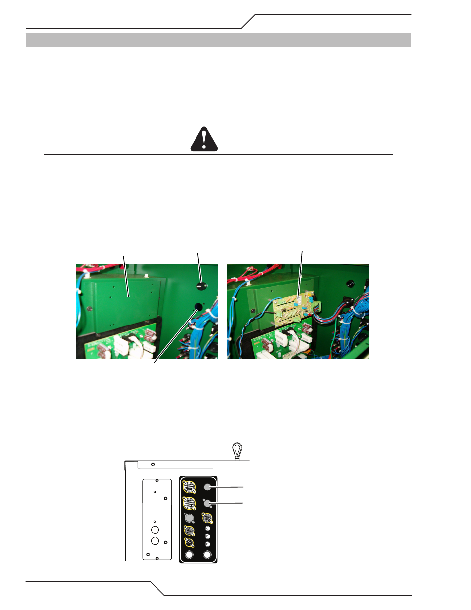
There is a space for mounting the V-D Board located on the upper portion of an internal vertical panel near the rear of the power
supply. Predrilled holes for mounting the iHT V-D board as well as another popular height control are provided.
CAUTION
If using another board that doesn’t align with the existing holes, remove the panel if possible before drilling. If not
possible then every precaution must be taken to keep metal filings from being deposited inside the power supply.
Install the V-D Board.
1. Locate the V-D Board which should be with the iCNC.
2. Inside the Power Supply, locate and remove the mounting panel’s 2 screws and panel.
3. Install the V-D board standoffs and the V-D Board from the XT iCNC then reattach the panel with the 2 screws, securing
the V-D board in place. If using another V-D Board, follow the instructions provided mounting it in this same location.
Space for V-D Board
Ohmic clip cable port
V-D Board connection
V-D Board installed
Art # A-12079
V-D Board shown with optional wire harness for iHC controller
Control Cable.
The iHC board can be supplied with a wire harness and connector (shown in previous image), to be installed in the rear panel hole
labeled “Height Control” . The connector mates with a cable from the iHC. For other height control V-D boards a strain relief can
be installed in this hole for those cables. Refer to Appendix for wiring diagram.
USER INPUT
HEIGHT CONTROL
F1 - 8A SB 230 VAC
F2 - 8A SB 230 VAC
CB4 - 5A 120 VAC
CB3 - 5A 24 VAC
CB2 - 5A 120 VAC
J55 - GCM
J15 - CNC
J59 - RAS
J70 - HE
J54 - TSC /COMM
Ohmic clip cable port
V-D Board connection
Art # A-12080