Ultra-cut 400 xt, Mc3a mc3b m1 – Tweco 400 XT Ultra-Cut Plasma Cutting System User Manual
Page 180
ULTRA-CUT 400 XT
A-72
APPENDIX
Manual 0-5275
Art # 12312
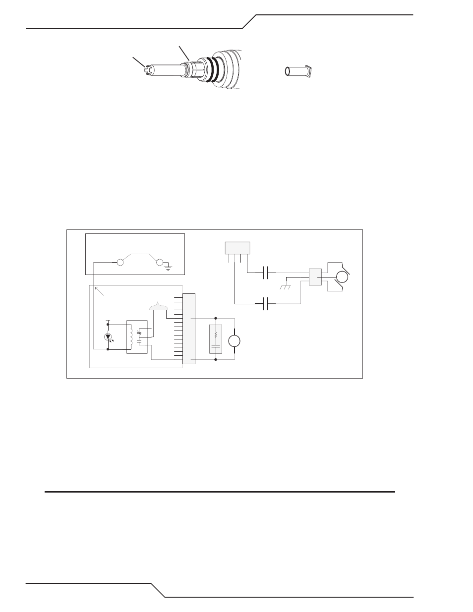
Coolant Tube Extension
Fingers
Internal Check Valve
No Power to the Pump Motor
The pump motor is powered by 230 VAC controlled by the MC3 control relay. During the � minutes after turning on power,
before the �0� fault code is displayed, measure for 230 VAC at the motor connector J1� pin 1 to pin 3.
a. If the pump motor is not getting 230 VAC, measure for 2� VAC on the coil of MC3. If present and the relay contacts aren’t
closed the relay is defective. Note, the coil is rectified so you won’t measure continuity of even a good coil.
b. If 2� VAC is not on the MC3 coil check for D27 on the relay board being ON. If it’s on the Relay board should be providing
the 2� VAC so if it’s not the Relay board may be defective. Measure for 2� VAC at J9-� to J9-12 on the Relay board. If
2� VAC is present and D27 is on, the Relay board or the wire harness is defective.
c. If D27 is not on, measure on the CCM I/O board between TP3 and the common at TP1. It should be low, near zero volts.
If not the CCM is probably defective. Jumper TP3 (I/O board) to TP1. If the pump comes on now replace the CCM.
d. If jumping TP3 to TP1 does not turn the fans on then the Relay board or the �0 pin ribbon cable pin 13 is at fault.
Art # 12313
MC3A
MC3B
M1
Torch Coolant Pump
1
2
3
J16
1
2
3
4
J13
(65B)
(66)
(67)
(64B)
CHASSIS GND
1
2
3
4
5
6
7
8
9
10
11
12
13
14
15
16
J8
1
5
3
2
4
Coolant Pump Control
K5
MC3
Coolant pump Control
(163)
(162)
SA4
ARC_SUPPRESSOR
D27
24 VAC
Relay PCB
TP1
TP3
CCM I/O PCB
To test Pump relay jump TP3 to TP1.
+24
J4-13
230 VAC from T1
Coolant flows but flow is less than the required minimum:
Test and adjust the pump/bypass valve:
This test measures the “dead head” or blocked flow pressure at the rear panel coolant supply fitting. Perform this test only
after the coolant system is fully primed, that is after the coolant is circulated throughout the system and is mostly free of
bubbles. It requires a pressure gauge with #� JIC fitting.
The gauge needs to be able to read at least 173 PSI. Remove the coolant supply hose and connect the pressure gauge in
its place. For the Auto-Cut 200 XT connect the gauge in place of the torch coolant supply hose on the torch connection
bulkhead. This is a #5 JIC fitting.
NOTE
Do not put the gauge in-line and attempt to pinch off the hose to block the flow. It is very difficult to totally
block the flow and failure to do so will result in incorrect setting of the bypass.
Turn the on the unit. You will have � minutes to perform the test/adjustment before the system times out with a coolant flow
fault. If that happens recycling the power gives you another � minutes.