Ultra-cut 400 xt, Mc2a mc2b, Fan1 – Tweco 400 XT Ultra-Cut Plasma Cutting System User Manual
Page 178
ULTRA-CUT 400 XT
A-70
APPENDIX
Manual 0-5275
403
Coolant overheated.
TS1 is a linear negative temperature coefficient (NTC) resistor sensor attached to the brass fitting at the exit of the bypass
valve. Here we determine the coolant being supplied to the torch is below the required temperature which is currently 75
deg C (1�7F). The radiator is on the lower right side of the unit. The fan(s) are behind it and blow out through the radiator.
100A & 200A units may either have 2 smaller fans or one larger one. The 300 & �00A units have one larger one.
Fans operate during cutting and for � minutes after last cut then shut off. Exception is AC 200 XT where the fans are on
whenever power is on. The external heat exchanger, HE�00, fan is thermostatically controlled so it only comes on when
coolant is over �0 deg C. It will shut off when the other fans shut off.
Possible reasons for coolant overheated:
Coolant fan(s) failed or defective fan control relay MC2.
• Radiator fins clogged with dirt.
• Duty cycle exceeded (ambient temperature above 40 deg C and operating at high duty cycle).
• Operating with an object placed in close proximity to the air outlet (right side of the unit) or the front panel inlet open-
ings.
• Operating for extended time with right lower side panel removed.
• Defective Relay board.
• Defective CCM.
Troubleshooting:
1. Check for air blowing out of the unit. Remember, except for the AC 200 XT, the fans only run when CNC START is applied
and for � minutes after cutting, you may have to apply start again to restart the � minute time. Fans may be forced on
by jumping TP2 on the CCM I/O board to TP1 (ground).
a. If using the external HE�00XT heat exchanger, optional for 300A, standard for �00A, check for air blowing out of it.
Note that the HE�00XT fan, controlled by a thermal switch in the HE�00XT, only runs if the coolant is over �0 deg
C and the internal fans are operating. With the 100 & 200A if it has 2 fans make sure both fans are operating by
checking for air both top and bottom of the opening. The fans are difficult to see, perhaps you can use an inspection
mirror. Be careful not to get the mirror or your hands into the blades.
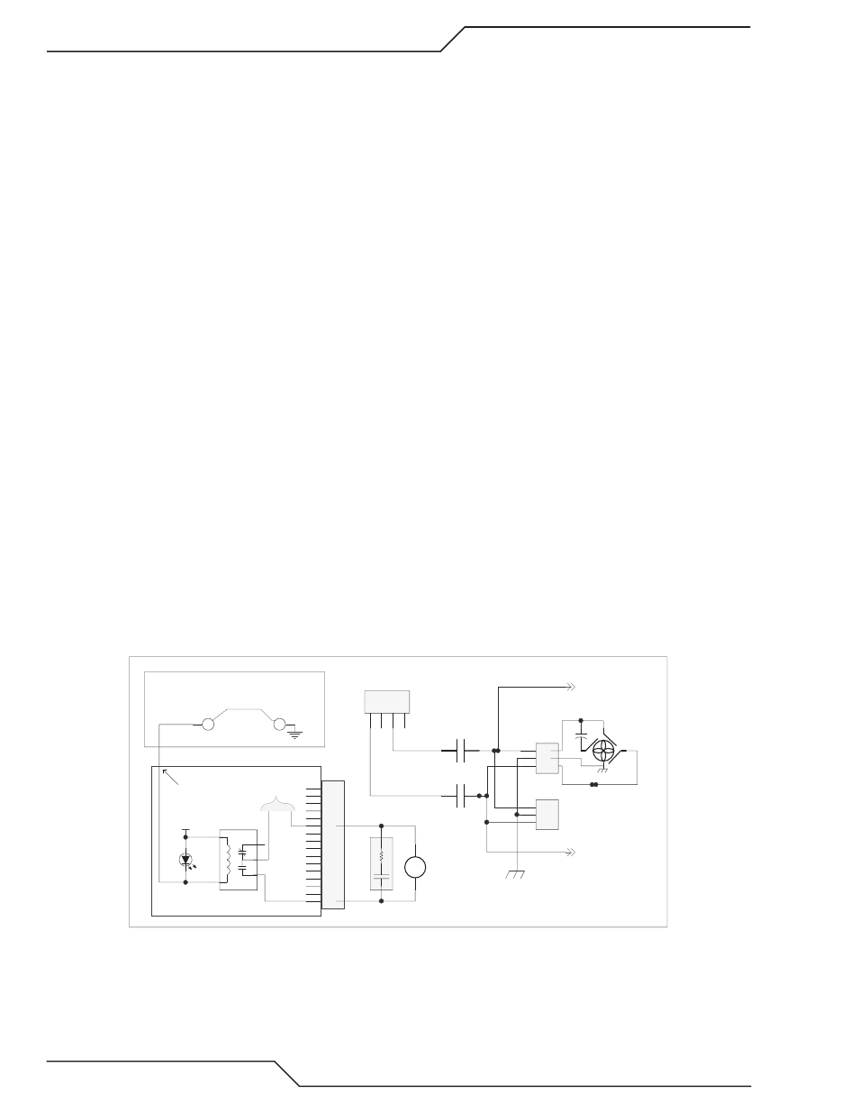
2. Fans are powered by 230 VAC. The 230 VAC for the fan(s) is switched by the MC2 control relay (except the AC 200 XT
where the fan(s) is powered directly from the T1 transformer at J13).
Art # 12311
1
2
3
4
5
6
7
8
9
10
11
12
13
14
15
16
J8
1
5
3
2
4
Fan Bias Control
K4
MC2
Fan Control
(160)
(161)
SA3
ARC_SUPPRESSOR
D24
24 VAC
Relay PCB
230 VAC from T1
MC2A
MC2B
To J70-2
To J70-3
(69)
(70)
(70)
(65A)
(70)
(69)
1
2
3
J73
(64A)
CHASSIS GND
1
2
3
J72
C4
FAN1
R
R
BK
BN
BL
1
2
3
4
J13
TP1
TP2
CCM I/O PCB
To test fan relay jump TP2 to TP1.
+24
J4-19