Ultra-cut 400 xt – Tweco 400 XT Ultra-Cut Plasma Cutting System User Manual
Page 163
ULTRA-CUT 400 XT
Manual 0-5275
APPENDIX
A-55
1
2
3
4
5
6
7
8
9
10
11
12
13
14
J62
1
2
3
4
5
6
7
8
9
10
11
12
13
14
J27
GND
+V
1
2
4
3
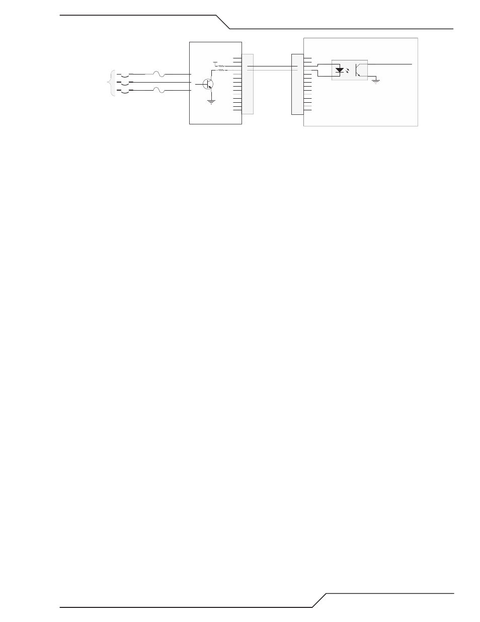
HCPL-817
U?
Missing Phase a
Missing Phase b
GND
To CPU PCB
J29-16
Missing Phase
I/O PCB
SYSTEM BIAS PCB
CB1
ON / OFF
F2
F1
J60-9,18
J60-5,14
J60-1,10
3 phase AC
Art # 12310
Normally when the phase is not missing the transistor is on which turns on the opto-isolator making the signal “Missing
Phase” low.
Causes for 201, missing phase code. Codes are displayed two different ways, with an “L” meaning “Latched” or “Last”, before
the number meaning it was a problem but isn’t right now or with an “E” meaning the problem exists now.
L201 :
Most likely cause is an intermittent problem with the incoming power or possibly a loose connection on the power cord at
the back or the Ultra-Cut or Auto-Cut plasma supply.
E201:
• Phase missing from the wall fuse box, blown fuse.
• F1 or F2, 8A 500V slow blow fuses blown.
• CB1 one phase open.
• System Bias board defective.
• I/O board defective.
Troubleshooting:
1. System Bias board has a red LED, D3, that lights if it detects a missing phase. If D3 is on, check J�0 for all 3 phases.
a. If all 3 phases are not present at J�0 check for incoming power, then the F1 & F2 fuses. Finally the CB1.
b. If all 3 phases present and about equal voltage then change the System Bias board.
2. If D3, Missing Phase LED, is not on check for voltage at J27-3 & � on the CCM. Normal voltage, with no missing phase,
at J27 (or J�2 on the System Bias board) pin 3 and pin �, relative to I/O PCB ground. (TP1) should be between 10-1�VDC
with pin 3 being a couple volts higher than pin �. If this is normal, problem may be in the CCM.
3. If the voltage at J27-3 & � is higher than 10-1�VDC and up to 20-2�VDC, make the same measurement at J�2 pin �. If
still high there and you have confirmed all 3 phases are present at J�0 then the System Bias is defective.
�. If the voltage at J�2-� is not high the wires between J27 and J�2 may be broken.
202-204 Not used. Reserved codes from the earlier product.
205
DC Output Low
DC output (voltage) low means one or more inverter sections are enabled but the output voltage is below a preset voltage.
Shortly after receiving the Start signal from the CNC, but before the end of preflow, both sections of IM#1 are enabled and
CCM measures the power supply output voltage between negative (Torch) to positive (Work) at the output terminals. If
this is less than a set value during preflow or if at any time during piloting or cutting it drops to below that value for a short
time, the inverters are shut off and code 205 is set. 205 will almost always be indicated as an “L”, not an “E” fault because
as soon as it’s detected the inverters are shut off and so no longer have the fault of low output voltage. Currently the low
voltage value is -�0VDC.
Causes of 205 code can include shorts outside the plasma power supply, shorts inside the plasma power supply and mea-
surement errors.
a. Short external to the plasma power supply: