Ultra-cut 400 xt – Tweco 400 XT Ultra-Cut Plasma Cutting System User Manual
Page 153
ULTRA-CUT 400 XT
Manual 0-5275
APPENDIX
A-�5
an inverter fault in Inverter 2A. This guide covers codes 2�7-252 in one section as they are all the same, varying only by which
inverter and section they refer to.
The codes are separated into � groups.
Group 1
Plasma Process -- Relating to pilot, transfer, torch voltages, etc.
Group 2
Plasma Power Supply -- Primarily the Inverter Sections
Group 3
Interface to Gas controls -- Mainly the DFC 3000
Group �
Cooling System -- The liquid cooling system for the torch and inverters
Group 5
CCM -- Communications port to the gas controls
For the XT units we are using a 3 digit code with group 1 codes in the 100’s, group 2 in the 200s etc. These correspond to the
older codes used in previous units, where 1-1 is now 101. For the most part the codes have the same meaning. Where an older
code no longer applies to the XT system we don’t use it over again and have left it reserved to avoid confusion. For example the
code 20� (2-�) which meant the inverter module wasn’t ready. We now detect that error in a different way that has a somewhat
different meaning so we have reserved the 20� Code.
While most of the codes indicate a fault has occurred, a few of them, such as 30� (formerly 3-�), simply refer to the current status.
30� indicates either “priming” where the pump is filling the system with coolant or more often “purging” where the gas is flowing
to dry the consumables after replacing them or purging the gas lines when a different gas type has been selected.
Troubleshooting (General)
In many cases where the cause may be listed as a cable or wire disconnected but also includes loose or broken.
All Ribbon cables have an extra receptacle near one end for measuring signals on the cable.
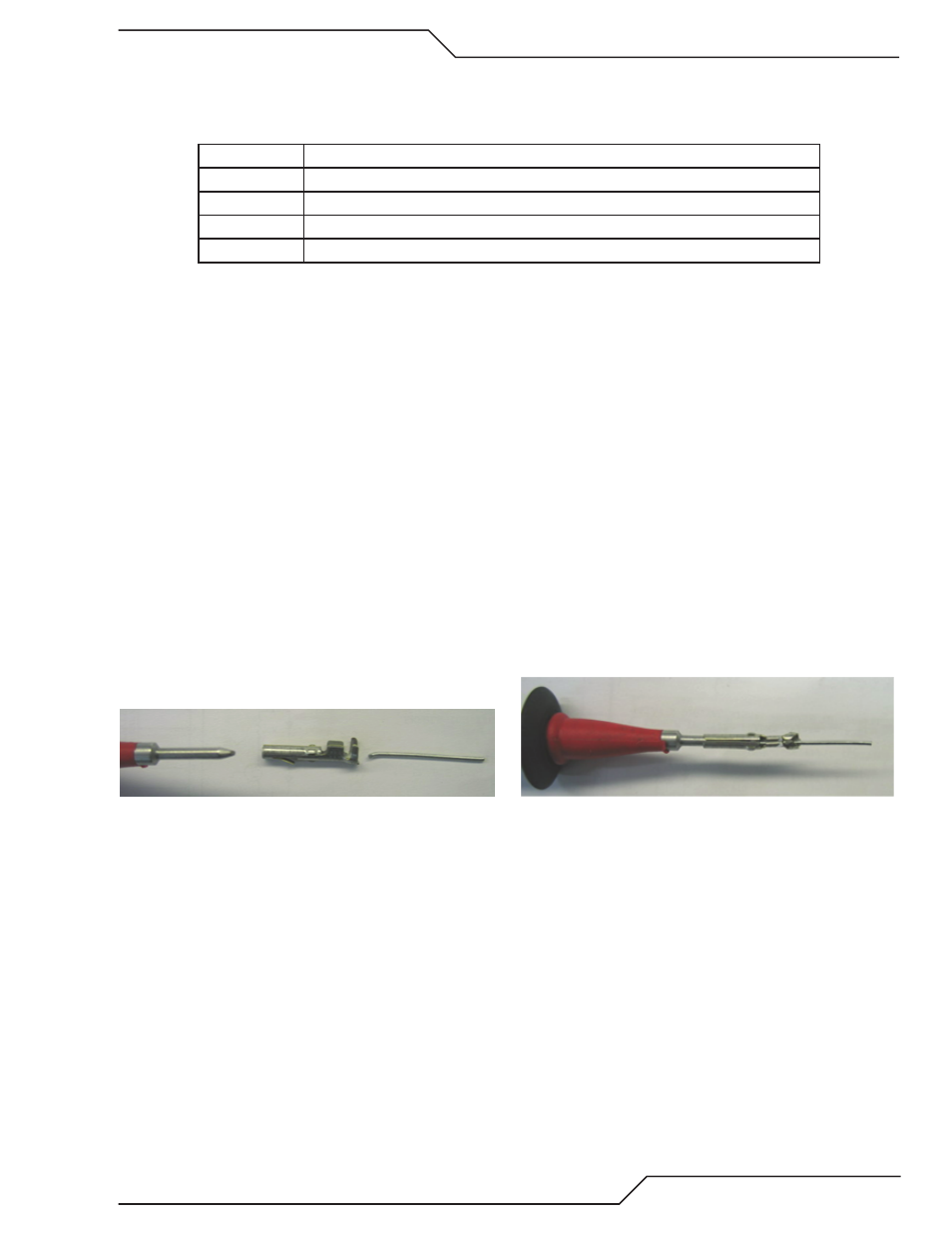
A number of the measurements will require probing of some small connectors or measuring signal on ribbon cables. For probing
the small connectors, standard meter probes are usually too big. We suggest making a couple probes using steel wire. Copper
buss wire isn’t stiff enough. A paper clip is a little too big. One idea is take a socket from an Amp mate-n-loc or similar connector
into which your meter probe will fit and crimp a small piece of steel wire, (0.020 to 0.025” dia.; (0.5-0.� mm) works best), into
where wire would normally be crimped. The wire should be soldered and crimped. The steel wire may be found in hobby stores
that cater to model building.
Art # 12302
Art # 12303
Insulate all but the end of the wire and slide these onto your meter probe. If your meter has alligator clip adaptors you could hold
the wire in these as well, be sure they don’t short together.
Problems that do not set Status or Fault codes:
1. At power on GAS LED blinks continuously, no code set. Real problem is no or low coolant flow but it takes � minutes
before code is set and people don’t wait that long.