06 system operation, 06 system operation -8, A. operational suggestions – Tweco 3000 Merlin User Manual
Page 40: B. using corner slowdown for mechanized cutting, C. setting csd output, D. drag mode feature, Figure 4-7 corner slowdown (csd) adjustment
OPERATION
4-8
Manual 0-2532
4.06 System Operation
NOTE
Frequently review the safety precautions at
the front of this manual.
This section contains operating information which is spe-
cific to the power supply. Detailed operating information
for torches can be found in the appropriate Torch
Instruc-
tion Manual.
WARNINGS
Disconnect primary power at the source be-
fore assembling or disassembling power sup-
ply, torch parts, or torch and leads assemblies,
or adding coolant.
It is not enough to simply move the ON/OFF
switch on the unit to OFF position when cut-
ting operations have been completed. Always
open the power supply disconnect switch five
minutes after the last cut is made.
A. Operational Suggestions
The suggestions below should be followed in all cutting
and gouging operations:
1. Wait five minutes before setting the ON/OFF switch
to OFF after operation. This allows the cooling fan to
run to dissipate operating heat from the power sup-
ply.
2. For maximum parts life, do not operate the pilot arc
any longer than necessary.
3. Use care in handling torch leads and protect them
from damage.
4. In continuous cutting applications using CO2, it is of-
ten necessary to manifold four to six cylinders together
to maintain adequate flow at operating pressures.
B. Using Corner Slowdown for Mechanized
Cutting
The corner slowdown (CSD) function provides a re-
duction in output current which corresponds with the
reduced travel speed of a mechanized torch as it
changes direction at a sharp corner. When activated
(by CNC or other control device) corner slowdown
eliminates excessive metal removal in corners.
Normally open (NO) contacts (supplied by the con-
trol device) close when the torch travel speed de-
creases through a corner. When the contacts close,
power supply output drops to a preset current level.
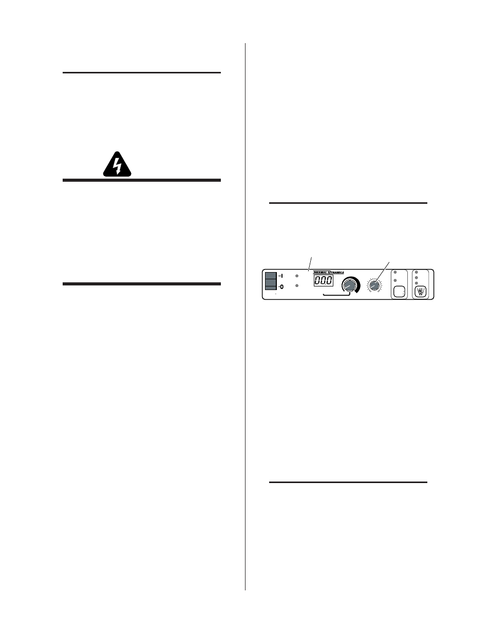
C. Setting CSD Output
NOTE
Corner Slowdown (CSD) is set at the RC6010
Remote Control.
OUTPUT AMPS
PLASMA
ENABLE
ON
START
REMOTE POWER SUPPLY CONTROL
CSD
(%)
0
25
75
100
50
TRAVEL
SPEED
125+
IPM
0-125
IPM
RUN
PURGE
SET
Front Panel of
RC6010 Remote Control
CSD (%)
Adjustment
A-00997
Figure 4-7 Corner Slowdown (CSD) Adjustment
The corner slowdown adjustment is located on the front
panel of the RC6010 Remote Control. The control sets
corner slowdown output to any current level from the
minimum (50 amps) to the maximum (150 amps) level
of the system. The corner slowdown output level is a
percentage of the main output level. Typically the CSD
output level should not be set lower than 70% of the main
current level to insure full arc penetration during corner
slowdown.
If the cutting machine controller activates CSD (three
decimals on the display) during pierce starts it may not
be desirable to set CSD below 100% as starting current
will be reduced requiring longer pierce times.
NOTE
For electrical connections, refer to Appendix
VI, CNC Interface Schematic
D. Drag Mode Feature
Should the torch tip contacts the workpiece the out-
put current will immediately drop to between 40 to
50 amps to minimize potential tip damage.