Tweco 3000 Merlin User Manual
Page 26
INSTALLATION
3-8
Manual 0-2532
The optional Two Stage Air Line Filter is shipped with the
following components:
• Air Line Filter Assembly (For Plasma Line) - 1 each
• Hex Nipples - 2 each
• 90° Female Elbow - 1 each
• 90° Street Elbow - 1 each
• Y-Hose Assembly - 1 each
Install the in-line air filter and connect the gas supply per
the following procedure:
1. Thread the first hex nipple into the 90° female elbow.
2. Thread the other end of the hex nipple into the outlet
of the air filter assembly. Tighten both sides securely.
3. Thread the second hex nipple into the fitting on the
rear panel marked PLASMA.
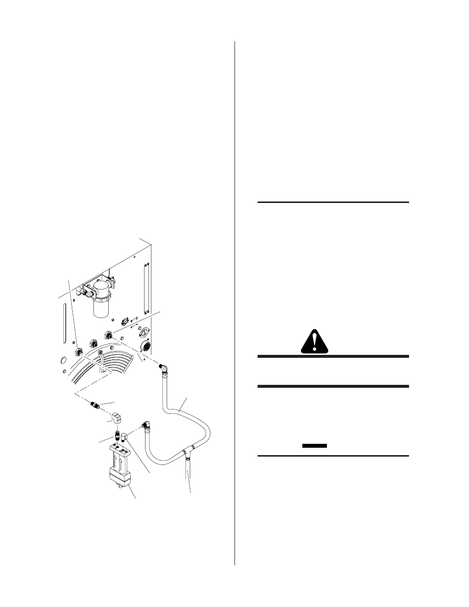
Secondary Gas
Fitting
Plasma Gas
Fitting
Y-Hose
Assembly
From Supply
Female Elbow
Street Elbow
Air Filter Assembly
(Plasma Line Only)
Hex Nipple
Hex Nipple
A-01007
Figure 3-9 Optional Two Stage Air Line Filter
Installation
4. Thread the 90° street elbow into the inlet side of the
air filter assembly.
5. Connect one side of the Y-hose assembly into the
other side of the 90° street elbow.
6. Thread the 90° female elbow onto the other end of
the second hex nipple. Fasten both sides securely.
7. Connect the other side of the Y-hose assembly to the
fitting on the rear panel marked SECONDARY.
8. Connect the supply line from the air supply source to
the Y-hose assembly. The supply hose must be 3/8
in (10 mm) minimum inside diameter to provide ad-
equate air flow.
B. Using High-Pressure Gas Cylinders
NOTES
Refer to the regulator manufacturer’s specifi-
cations for installation and maintenance pro-
cedures. Refer to Section 6.05, System Op-
tions and Accessories, or a listing of available
high-pressure regulators.
Do not use an air line filter with high pressure
gas cylinders.
1. Examine the cylinder valves to be sure they are clean
and free of oil, grease or any foreign material. Mo-
mentarily open each cylinder valve to blow out any
dust which may be present.
WARNING
Do not stand in front of the valve outlet when
opening.
2. Each cylinder must be equipped with an adjustable
high-pressure regulator capable of pressures up to
125 psi (8.6 BAR) maximum and flows of up to 700
scfh (328 lpm) for cutting or gouging.
CAUTION
Maximum input pressure to the internal regu-
lator on the Power Supply must not exceed
125 psi (8.6 BAR).
Connect the gas supply to the Power Supply per the fol-
lowing:
1. Connect the black supply hose from the plasma
gas regulator directly to the input fitting on the
rear panel of the Power Supply marked PLASMA.