09 work cable and ground connections, 09 work cable and ground connections -5 – Tweco 3000 Merlin User Manual
Page 23
Manual 0-2532
3-5
INSTALLATION
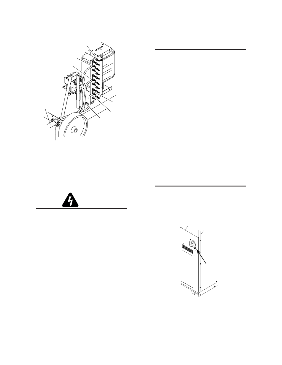
Input Voltage
Terminal Board
L1
L2
L3
Primary Power
Cable
Strain Relief
Fitting
Ground
Connection
Busbars
A-00893
Figure 3-6 Input Voltage Connections
2. Connect the electrical ground wire to the ground
lug on the base of the unit.
WARNING
The electrical ground wire must be connected
to the ground lug in the base of the unit for
proper grounding.
3. Connect the three line leads to the input voltage
terminal board per the following:
• Line 1 to terminal L1.
• Line 2 to terminal L2.
• Line 3 to terminal L3.
4. Tighten all nuts.
3.09 Work Cable And Ground
Connections
NOTE
Refer to Appendix III for a block diagram of a
typical mechanized system work and ground
cable connections.
A. Electromagnetic Interference (EMI)
Pilot arc initiation generates a certain amount of electro-
magnetic interference (EMI), commonly called RF noise.
This RF noise may interfere with other electronic equip-
ment such as CNC controllers, remote controls, height
controllers, etc. To minimize RF interference, follow these
grounding procedures when installing mechanized sys-
tems:
B. Grounding
1. The preferred grounding arrangement is a single point
or “Star” ground. The single point, usually on the cut-
ting table, is connected with 1/0 AWG (European 50
mm
2
) or larger wire to a good earth ground (refer to
paragraph ‘C’, Creating An Earth Ground). The ground
rod must be placed as close as possible to the cutting
table, ideally less than 10 ft (3.0 m), but no more than
20 ft (6.1 m).
NOTE
All ground wires should be as short as pos-
sible. Long wires will have increased resis-
tance to RF frequencies. Smaller diameter
wire has increased resistance to RF frequen-
cies, so using a larger diameter wire is better.
A-00986
Grounding
Stud
Figure 3-7 Power Supply Earth Grounding Stud
Location