12 external cable connections, 12 external cable connections -12, A. optional rc 6010 remote control – Tweco 3000 Merlin User Manual
Page 30: B. computer control interface (cnc)
INSTALLATION
3-12
Manual 0-2532
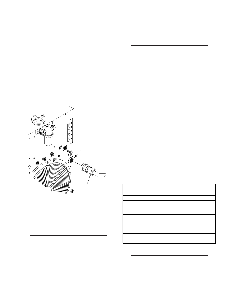
3.12 External Cable Connections
Depending on the options installed there are various
cables to be connected the Power Supply.
A. Optional RC 6010 Remote Control
For mechanized systems, the optional RC 6010 Remote
Control allows the operator to control all system func-
tions from a remote location. The control cable to inter-
face the RC 6010 to the Power Supply is available in
various lengths (Refer to Section 6.04, Options and Ac-
cessories).
1. Connect the control cable to the receptacle
marked REMOTE CONTROL (J15) on the rear
panel of the Power Supply.
OUTPUT
TO
CONTROL
MODULE
AIR
PLASMA
INPUT
N
2
PLASMA
INPUT
O
2
PLASMA
INPUT
PLASMA GAS
Ar/H
Ar/H
2
PLASMA
INPUT
A-01004
Cable From
Remote Control
REMOTE CONTROL
Connector (J15)
Figure 3-17 Remote Control Interface Connection
2. Connect the other end of the control cable to the
receptacle marked PS (J37) on the rear panel of
the remote control.
NOTE
Refer to the RC 6010 Remote Control Instruc-
tion Manual 0-2478 for more information on
the RC6010 Remote Control including CNC.
B. Computer Control Interface (CNC)
The computer control interface allows a mechanized sys-
tem to interface with a computer or other control device.
NOTE
Refer to Section 4.03-D for more information
on the CNC connections.
CNC cables can be interfaced to the Power Supply using
one of the following methods:
• Connector (J15) at the rear of the Power Supply
• Internal terminal strip in the Power Supply
Depending on the equipment ordered and the cables sup-
plied connect the CNC cable per one of the following:
1. Using supplied CNC cable
Connect the supplied Power Supply/CNC Cable
to the Power Supply rear connector J15 labelled
REMOTE CONTROL.
2. Using customer supplied CNC Cable
a. Remove the Left Side Panel from the Power
Supply as viewed from the front of the unit.
b. Locate the internal terminal strip (TB2) near
the heatsink.
c. Feed the CNC cable through the small strain
relief at the rear of the Power Supply.
d. Connect the CNC cable to the terminal strip
(TB) per the following chart:
TB
Connection
Description
1
One Side of Enable Signal
2
Other Side of Enable Signal
3
One Side of START(Low)/STOP (High) Signal
4
Other Side of START (Low)/STOP (High) Signal
5
Not Used
6
Not Used
7
One Side of Pilot Sensing Relay (PSR)
8
Other Side of Pilot Sensing Relay (PSR)
9
One Side of OK-To-Move Signal
10
Other Side of OK-To-Move Signal
NOTES
Connections to TB positions 1 through 8 are
activated with a switch or contact closure.
If Remote Control is not used the Enable Sig-
nal circuit must be closed.