Tweco 3000 Merlin User Manual
Page 24
INSTALLATION
3-6
Manual 0-2532
2. Grounding for components mounted on the cutting
table (CNC controllers, height controllers, plasma re-
mote controls, etc.) should follow the manufacturer’s
recommendations for wire size, type, and connection
point locations.
For Thermal Dynamics components it is recom-
mended to use a minimum of 10 AWG (European 6
mm
2
) wire or flat copper braid with cross section equal
to or greater than 10 AWG connected to the cutting
table frame. The connection point must be clean bare
metal; rust and paint make poor connections. For all
components, wires larger than the recommended mini-
mum can be used and may improve noise protec-
tion.
3. The cutting machine frame is then connected to the
“Star” point using 1/0 AWG (European 50 mm
2
) or
larger wire.
4. The plasma power supply work cable (see NOTE) is
connected to the cutting table at the single point “Star”
ground.
NOTE
Do Not connect the work cable directly to the
ground rod.
5. Make sure work cable and ground cables are prop-
erly connected. The work cable must have a solid
connection to the cutting table. The work and ground
connections must be free from rust, dirt, grease, oil
and paint. If necessary grind or sand down to bare
metal. Use lock washers to keep the connections
tight. Using electrical joint compound to prevent cor-
rosion is also recommended.
6. The plasma power supply chassis is connected to the
power distribution system ground as required by elec-
trical codes. If the plasma supply is close to the cutting
table (see NOTE) a second ground rod is not usually
needed, in fact it could be detrimental as it can set up
ground loop currents that cause interference.
When the plasma power supply is far away from the
ground rod and interference is experienced, it may
help to install a second earth ground rod next to the
plasma power supply. The plasma power supply
chassis would then be connected to this ground rod.
NOTE
It is recommended that the Plasma Power
Supply be within 20 - 30 ft (6.1 – 9.1 m) of the
cutting table, if possible.
7. The plasma control cable should be shielded with the
shield connected only at the cutting machine end.
Connecting the shield at both ends will allow ground
loop currents which may cause more interference than
with no shield at all.
C. Creating An Earth Ground
1. To create a solid, low resistance, earth ground, drive
a 1/2 in (12 mm) or greater diameter copper clad
ground rod at least 6 - 8 ft (1.8 - 2.4 m) into the earth
so that the rod contacts moist soil over most of its
length. Depending on location, a greater depth may
be required to obtain a low resistance ground (see
NOTE). Ground rods, typically 10 ft (3.0 m) long,
may be welded end to end for greater lengths. Lo-
cate the rod as close as possible to the work table.
Install a ground wire, 1/0 AWG (European 50 mm
2
) or
greater, between the ground rod and the star ground
point on the cutting table.
NOTE
Ideally, a properly installed ground rod will have
a resistance of three ohms or less.
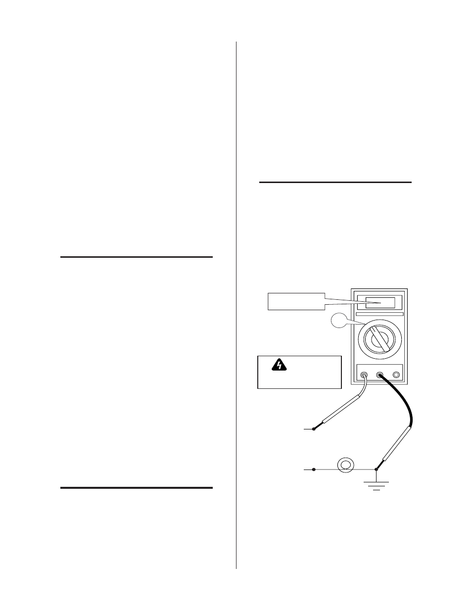
To test for a proper earth ground, refer to the follow-
ing diagram. Ideally, the reading on the multimeter
should be as follows:
• For 115VAC: 3.0 VAC
• For 230VAC: 1.5 VAC
Art # A-02971
+
_
Meter set to
VAC setting
Neutral
Line (Hot)
100W
Light Bulb
115 or 230VAC
WARNING
Use extreme caution. This
test uses live voltage.
115VAC: 3.0 VAC
230VAC: 1.5 VAC
V
~
V
~
VR COM A
Ground
Rod
Ground Testing