Section 2: introduction, 01 scope of manual, 02 general description – Tweco 3000 Merlin User Manual
Page 15: 03 specifications & design features, Section 2, Introduction -1
Manual 0-2532
2-1
INTRODUCTION
SECTION 2:
INTRODUCTION
2.01 Scope of Manual
This manual contains descriptions, operating instructions
and basic maintenance procedures for the Merlin 3000
Plasma Cutting Power Supply. Service of this equip-
ment is restricted to Thermal Dynamics trained person-
nel; unqualified personnel are strictly cautioned against
attempting repairs or adjustments not covered in this
manual, at the risk of voiding the Warranty.
Read this manual thoroughly. A complete understanding
of the characteristics and capabilities of this equipment will
assure the dependable operation for which it was designed.
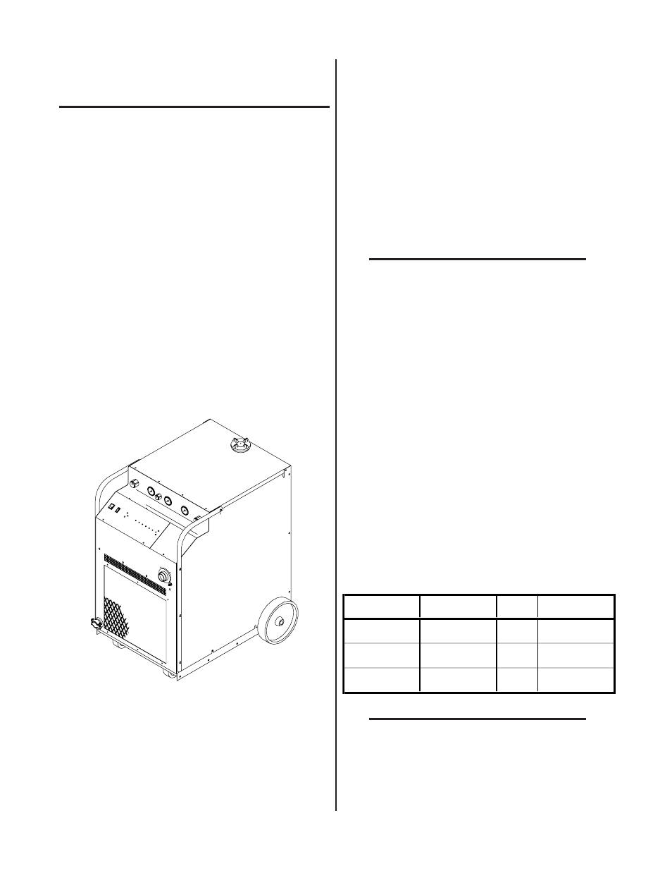
2.02 General Description
The Power Supply contains all operator controls, electri-
cal and gas inputs and outputs, and the torch leads re-
ceptacle. Many options and accessories can be added
to further improve the versatility of the system.
A-00907
Figure 2-1 Power Supply
The Standard Coolant supplied with the Power Supply
can be used in ambient temperatures down to 10° F
(-12° C). If the ambient temperature will be below 10°
F (-12° C) then Super Coolant should be used. This cool-
ant can be used in areas where the ambient temperature
drops to -27° F (-33° C).
A typical system configuration will contain the following:
• Power Supply with Running Gear and Handles
• Arc Starter Box
• Maximizer 300 Machine Torch with Mounting
Assembly
• Torch with Leads
• Torch Leads Extension
• Maximizer 300 Spare Parts Kit
• 25 ft (7.6 m) Work Cable and Clamp
• Air Line Filter Assembly (or) High Pressure Regu-
lators
NOTE
Refer to Section 2.05 for complete list of Power
Supply Options and Accessories.
2.03 Specifications & Design
Features
The following apply to the Power Supply only:
1. Controls
ON/OFF Switch, Output Current Control, RUN/SET/
PURGE Switch, Secondary Gas Regulator, Plasma
Gas Regulator, Secondary Mode Switch
2. Control Indicators
LED Indicators:
AC , TEMP, GAS, DC, PILOT, COOLANT PRES, and
COOLANT COND
Gauges:
Secondary, Plasma, and Coolant Pressure Gauges
3. Input Power
Voltage
Frequency
Phase
Amperage
200/220/230
50 or 60 Hz
3
98/89/85
380/415/460
50 or 60 Hz
3
51/47/42
500/575
50 or 60 Hz
3
40/34
NOTE
Refer to Appendix I for recommended input
wiring size, current ratings, and circuit protec-
tion requirements.
Amps depends on input voltage (Refer to Appendix I).