SoundOff Signal R4 Series Recess Mount User Manual
R4 series led light erdrebz3(xx), Warning
E36REBB3(XX) 11.06
R4 SERIES LED LIGHT
ERDREBZ3(xx)
WARNING: Warning devices are strictly
regulated and governed by Federal, State, and
Municipal ordinances. These devices shall be
used ONLY on approved vehicles. It is the sole
responsibility of the user of these devices to
ensure compliance.
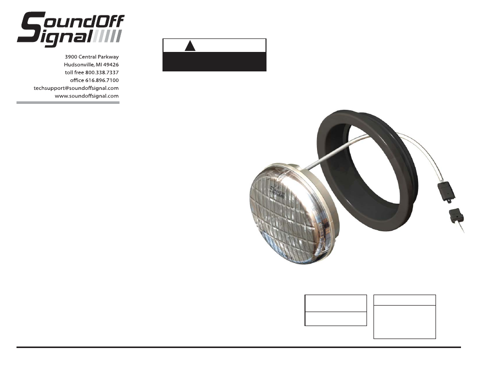
GROMMET MOUNTING
1. Cut a 4-1/2” hole in vehicle if needed.
2. Push Rubber Grommet into hole until it
seats
3. Feed wires through hole and connect the
wires to user supplied switching unit inside
vehicle.
4. Push the light into grommet until it seats.
The word “Top” must be positioned at the
top of the light.
OPERATING INSTRUCTIONS
The R4 Series LED light comes equipped
with its own selectable 16 pattern flasher
or it can be put into slave mode and driven
through an external flasher.
1. Connect the BLACK wire to a good,
convenient ground.
2. Connect the RED wire to one side of user
supplied on/off switch. Connect the other
side of the switch, through a 5 Amp fuse,
to a source of +10-16Vdc.
!
WARNING
This product contains high intensity LED
devices. To prevent eye damage, DO NOT
stare into light beam at close range.
PATTERN SELECTION
1. Turn light ON.
2. Touching and removing the WHITE wire to
ground will advance the light to the next
flash pattern. See flash pattern table.
Continuing to touch and remove the
WHITE wire to ground will allow you to
scroll through the pattern list. After pattern
#16 is reached the list will start over again
at pattern #1.
Note: The R4 Series LED Light is equipped
with a flash pattern memory. Once you
have selected a pattern, the light will
always activate to that pattern every time
the unit is turned on. Tape and secure
WHITE wire so that it will not accidentally
change your selected pattern.
SLAVE MODE
The R4 Series Light is capable of being
activated through the use of a user
supplied flasher by putting it in slave
mode.
1. Permanently connect the WHITE
to a good, convenient ground.
2. Connect the RED wire, through a
5 Amp fuse, to the output of a
+10-16Vdc switching flasher.
IMPORTANT: DO NOT
connect
this device to a strobe power supply
WIRE HOOK-UP TABLE
Wire Color
Connect to:
Red
+9-16Vdc
Black Ground
(-)
White ID/Pattern
Select
CURRENT DRAW AT
12.8Vdc
1 Amp (All configs.)