SoundOff Signal Mighty Night Light SM User Manual
Warning, Surface mount led spotlight
To review our Limited Warranty Statement & Return Policy for this or any SoundOff Signal product please visit our website at www.soundoffsignal.com and select the “Warranty & Returns”
link along the left column of our home page. If you have questions regarding this product please contact Technical Services, Monday - Friday, 8 am to 5 pm at 1.800.338.7337, press #4 to
skip the automated message. Questions or comments that do not require immediate attention may be emailed to [email protected].
1.800.338.7337. / www.soundoffsignal.com / Thank you for trusting us with your safety!
Important!
The cable from the back
of the light must be straight and relaxed
for approximately the fi rst inch. This is
necessary to maintain the integrity of
the light and comply with warranty.
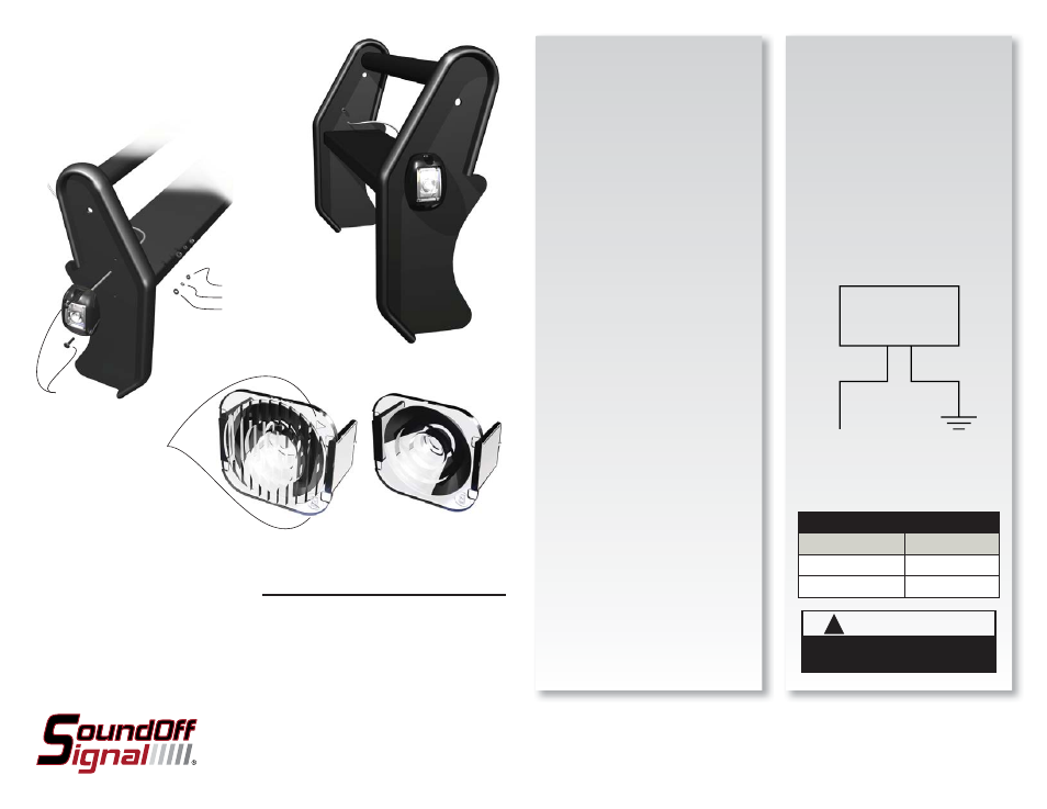
OPERATION:
Connect RED wire to +10-30Vdc source
either direct or through a fl asher (see
recommended fl asher on reverse side).
Connect BLACK wire to ground (-).
Wire Diagram
See reverse side for recommended
fl asher
SURFACE MOUNT LED SPOTLIGHT
EAUSSMBØSWC - WITH SPOT LENS
EAUSSMBØAWC - WITH REFRACTIVE LENS
!
WARNING
This product contains high intensity LED devices.
To prevent eye damage, DO NOT stare into the
light beam at close range.
Please see reverse for
Technical Specifi cations
• Warning devices are strictly regulated and governed by Federal, State and Municipal ordinances.
These devices shall be used ONLY on approved vehicles. It is the sole responsibility of the user of these
devices to ensure compliance.
• DO NOT connect this device to a strobe power supply. This product is self-contained and does not
require an external power supply.
EAUSSMBØ(x)WC 2.10
Important Information:
INSTALLATION:
The orientation of the SURFACE MOUNT
LED SPOTLIGHT is optional if the spot
lens (EAUSSMBØSWC) is installed.
The light may be inverted or installed
horizontally. If the refractive lens
(EAUSSMBØSWC) is used the arrows
must point to the front of the vehicle for
proper installation.
1) Determine a clean, fl at location on
the vehicle to mount the SURFACE
MOUNT LED SPOTLIGHT.
2) Using the template provided on the
reverse side of this page mark and
drill appropriate holes as shown on
the same surface that the warning
light will be in contact with. Note that
every effort has been made to make
a full scale template but variances
may occur. It is the responsibility
of the installer to ensure accurate
dimensions.
3) Drill the 2-
7/32” holes for the 10-24
carriage bolts.
4) Drill a
3/8” hole for the cable to pass
through the web of the push bumper.
Note: this hole must be free of burrs
and sharp edges to prevent damage
to the wires.
5) Insert cable through
3/8” hole and
insert carriage bolts through
7/32”
holes.
6) Place fl at washer, lock washer and
nut on carriage bolts and tighten
using reasonable force. DO NOT
OVER-TIGHTEN!
7) Make electrical connections.
NUT
LOCK WASHER
FLAT WASHER
CARRIAGE
BOLTS
ARROWS ON REFRACTIVE
LENS (EAUSSMBØAWC)
MUST POINT FORWARD OF
VEHICLE. THIS DIRECTS LIGHT
APPROX. 15° FORWARD
WIRE HOOK-UP TABLE
WIRE COLOR:
CONNECT TO:
RED
+10-30Vdc
BLACK
Ground (-)
+10-30Vdc
Ground (-)
PUSH BUMPER
WARNING LIGHT
RED
BLACK
SPOT LENS (EAUSSMBØSWC)
ALTHOUGH THIS LIGHT IS SHOWN MOUNTED TO A
PUSH BUMPER IT CAN ALSO BE MOUNTED TO ANY
FLAT SURFACE WHERE SPOT LIGHTING IS REQUIRED.