SoundOff Signal Universal Undercover Push-In LED Insert User Manual
Page 2
Parts & Accessories:
PLUC2LN1E - LENS #1, Extreme Angle
PLUC2LN1V - LENS #2, Vertical Output
PLUC2LN1H - LENS #3, Horizontal Output
PLUCPGR1 - GROMMET
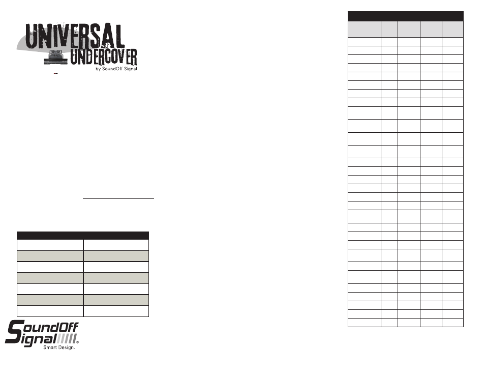
TECHNICAL SPECIFICATIONS
Overall Dimensions:
1.5" n x 0.9" H
Flash Patterns:
30 flash patterns
Input Voltage Range:
+Vdc
Current Consumption:
<1 Amp / module
# of LEDs:
6 Gen3 LEDs
Light Sync Technology:
Yes
Operating Temp.:
-40º to +65º C
*Flash Pattern Dependent
PATTERN RESET
1. Remove power.
2. Place WHITE (sync) wire to ground.
3. With sync wire grounded, re-power RED wire.
4. Maintain for one second (light will dim).
5. Remove power and ground (pattern 1 set).
SLAVE MODE
The UNDERCOVER is capable of being activated through the use
of a user supplied flasher by putting it in slave mode.
1. Permanently connect the UNDERCOVER™ WHITE and BLACK
wire to a good, convenient ground.
2. Connect the UNDERCOVER™ RED wire, through a 3Amp fuse,
to the output of a +Vdc switching flasher.
Flash Patterns
Pattern Name
1 Light
Alternating
2 Lights
Simultaneous
2 Lights
F.P.M.
(Flashes /
Minute)
1. Quint
x
x
x
70
2. Warp
x
x
x
350
3. Inter-Cycle Flash
x
x
4. Double Flash
x
x
x
70
5. Quad Flash
x
x
x
80
6. PowerPulse™
x
x
x
180
7. RoadRunner™
x
x
x
113
8. Q-Switch™
x
x
9. RoadRunner™
Steady Burn
x
x
113
10. Quad Steady
Burn
x
x
80
11. E-Ideal Single
Flash
x
x
x
200
12. E-Ideal Double
Flash
x
x
x
146
13. Quad2 Flash
x
x
x
67
14. Double2 Flash
x
x
x
95
15. PowerRunner
x
x
x
16. LCR Quint
x
x
x
17. Warp
3
x
x
x
18. Ultra Warp
x
x
x
545
19. Thunder &
Lightning
x
x
20. Lite Speed
x
x
x
85
21. SuperSonic
x
x
170
22. LCR Lite Speed
x
x
x
23. SuperSonic
Ultra
x
x
x
24. Tempo Shift
x
x
x
25. Tempo Shift
Warp
x
x
x
26. SBE2
x
x
x
67
27. C
2
x
x
x
200
28. U
2
x
x
x
176
29. Cyclone
x
x
x
30. Chameleon2`
x
x
x
SINGLE LIGHT HEAD SET UP AND PATTERN SELECTION
1. Disconnect WHITE wire from any connections if applicable.
2. Turn UNDERCOVER™ ON by applying power to RED.
3. Momentarily touching and removing the WHITE wire to ground will
advance the UNDERCOVER™ to the next flash pattern. Touching and
removing the WHITE wire for more than a few seconds will allow you to
change the UNDERCOVER™ to the previous pattern. See flash pattern table.
Continuing to touch and remove the WHITE wire to ground will allow you to
scroll through the pattern list. After pattern #30 is reached the list will start
over again at pattern #1.
SINGLE COLOR AND DUAL COLOR CONFIGURATIONS
Follow the ID selection steps and set the UNDERCOVER to the
following ID:
ID #1 - Split Color
ID #3 - Split Color
ID #2 - Single Color
ID #4 - Single Color
Single Color - Simultaneous Flash Patterns:
- Set light heads to same ID (#2 or #4).
Single Color - Alternating Flash Patterns:
- Set one light head to ID #2 and another to ID #4.
Split Color - Simultaneous Flash Patterns:
- Set light heads to the same ID (#1 or #3).
Split Color - Alternating Flash Patterns:
- Set one light head to ID #1 and another to ID #3.
MULTIPLE LIGHT HEAD SET UP AND PATTERN SELECTION
1. Set ID#
a. Connections
i. RED: +Vdc
ii. WHITE: +Vdc (Note: you will need to disconnect after power is
applied)
iii. BLK: Ground
iv. GREEN: NO CONNECTION REQUIRED FOR ID SELECTION
b. Apply power to unit
c. Without disconnecting power from unit, disconnect WHITE wire
d. Momentarily connect WHITE to Ground to change ID #
i. Identify ID# by number of sequential flashes
ii. Possible ID#s: 1 – 4
e. Disconnect Power to exit ID mode
2. Set Pattern - Must be done individually to each light prior to syncing
a. RED: +Vdc
b. BLACK: Ground
c. While light is powered, tap WHITE wire to ground to advance to the
next pattern (SEE pattern table at right)
d. Disconnect Power
3. Sync Lights
a. Once desired pattern has been selected for all light heads connect all
white wires and insulate with electrical tape.
4. Connect Master Switch for Application.
Maximum Light heads that can be synchronized together
is 4 without external flasher available from SoundOff Signal.
ELUCP(x)0(xx)(x) 3.13
1.800.338.7337 / www.soundoffsignal.com
2.