SoundOff Signal Universal Undercover LED Insert User Manual
Warning, Universal undercover™ led insert, Warning-hot
To review our Limited Warranty Statement & Return Policy for this or any SoundOff Signal product please visit our website at www.soundoffsignal.com and select the “Warranty & Returns”
link along the left column of our home page. If you have questions regarding this product please contact Technical Services, Monday - Friday, 8 am to 5 pm at 1.800.338.7337, press #4 to
skip the automated message. Questions or comments that do not require immediate attention may be emailed to [email protected].
1.800.338.7337. / www.soundoffsignal.com / Thank you for trusting us with your safety!
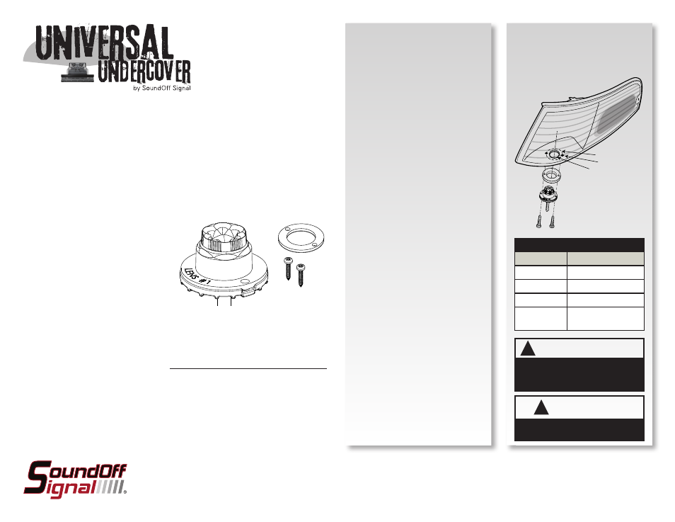
9. Complete wire connections and
test light prior to remounting vehicle
reflector assembly
10. Re-install reflector assembly
according to vehicle manufacturer’s
instructions.
Please see reverse for Technical
Specifications and Illustrations
• DO NOT cut the wires between in-line flasher and light head
• Warning devices are strictly regulated and governed by Federal, State and Municipal ordinances.
These devices shall be used ONLY on approved vehicles. It is the sole responsibility of the user of these
devices to ensure compliance.
• DO NOT install this product or route any wires in the Air Bag Deployment Zone. Refer to your vehicle
Owner’s Manual for the location of any air bag deployment zones.
• DO NOT connect this device to a strobe power supply. This product is self-contained and does not
require an external strobe power supply.
ELUC2(w)Ш1Ш(x) 6.11
Important Information:
MOUNTING INSTRUCTIONS
Up to 4 LED inserts can be synchronized
for alternating or simultaneous flash
patterns using the white (SYNC) wire.
See back for SYNC Configuration
instructions.
1. Remove the reflector assembly
according to the vehicle
manufacturer’s instructions.
2. Establish a location for each
UNDERCOVER™ light head with the
following parameters:
a. Light head must have 1” clearance
from plastic/lens surfaces.
b. Light head does not interfere with
normal operation of lamp.
c. Choose a surface that is flat
as possible for good sealing when
light head is installed.
d. For greatest reflector fill and
efficiency, place the light as close
to the focal point of the reflector
as possible.
3. When removing optic lenses, use
small flat head screw driver to
carefully pry lens off assembly. When
replacing lens, do not touch LEDs or
circuit board.
4. Using a 1” hole saw, drill a hole
in reflector housing in the location
selected in step 2.
5. Place UNDERCOVER™ insert into
hole drilled in step 5. Using the light
as a template, mark the two mounting
hole locations.
6. Drill holes marked in step 6 with a
#40 (0.098”) drill bit.
7. Install UNDERCOVER™ LED Insert
assembly using the gasket and #6
screws provided.
WIRE HOOK-UP TABLE
WIRE COLOR:
CONNECT TO:
RED
+Vdc
BLACK
Ground (-)
WHITE
Pattern Select/Sync
GREEN
Cruise Mode
(+Vdc)
UNIVERSAL UNDERCOVER™
LED INSERT
ELUC2SШ1Ш(x) - 10-16 Vdc, 10' CABLE
ELUC2SØ25(x) - 10-16 Vdc, 25' CABLE
ELUC2HШ1Ш(x) - 10-30 Vdc, 10' CABLE
KIT INCLUDES:
1 ea. - Assembled light head with Extreme Angle
Lens #1, in-line flasher and desired cable length
1 - EPDM Mounting Gasket
2 - Mounting Screws
Drill #40 hole
1 1/4 inch spacing
1 inch dia. hole
WIRE CONNECTIONS
WARNING-HOT!
!
This product must be mounted with sufficient
clearance from any plastic parts. Failure to
do so may result in permanent damage to
the housing.
!
This product contains high intensity LED
devices. To prevent eye damage, DO NOT
stare into the light beam at close range.
WARNING