Single multi-mount ece65 certified w/ xylex lens – SoundOff Signal GHOST Multi Mount ECE User Manual
Page 2
1.800.338.7337 / www.soundoffsignal.com
EGHSTE1(x) 07.14
ONE (1) LIGHT
Single Light Operation: Follow the ID Selection steps and set the
ECE GHOST to ID#1 if it is not already.
TWO (2) LIGHTS
ALTERNATING: To obtain Alternating patterns, follow the ID
SELECTION steps and set one ECE GHOST to ID#1 and the other
to ID#3. Then proceed to the PATTERN SELECTION steps.
SIMULTANEOUS: To obtain Simultaneous patterns, follow the ID
SELECTION steps and set both ECE GHOST lights to ID#1. Then
proceed to PATTERN SELECTION steps.
SLAVE MODE
The GHOST is capable of being activated through the use of a use
supplied flasher by putting it in slave mode.
1. Permanently connect the GHOST WHITE and BLACK wire to a
good, convenient ground.
2. Connect the GHOST RED wire, through a 5Amp fuse, to the output
of a +10-30Vdc switching flasher.
PATTERN RESET
1. Remove power
2. Place WHITE (sync) wire to ground
3. With sync wire grounded, re-power RED wire
4. Maintain for one second (light will dim)
5. Remove power and ground (pattern 1 set)
ECE GHOST Sync Configuration Instructions
IMPORTANT! A MAXIMUM OF 4 SINGLE LIGHTS
CAN BE SYNCED TOGETHER
1. Set ID#
a. Identify which pattern and sequence you want and look up ID#
settings at right.
b. Connections
i. RED:
+12Vdc
ii. WHT: +12Vdc (Note: you will need to disconnect after
power is applied)
iii. BLK:
Ground
c. Apply power to unit
d. Without disconnecting power from unit, disconnect WHT
wire
e. Momentarily connect WHT to Ground to change ID #
i. Identify ID# by number of sequential flashes
ii. Possible ID#s: 1 – 4
f. Disconnect power from unit to get out of ID mode.
2. Set Pattern
a. Reapply power to units.
b. Once all Light Head ID#s are configured, make sure all
lights are flashing the same pattern
c. Connect corresponding colored wires of all units together:
RED to RED, etc.
d. Change Pattern
i. Momentarily touch WHT wires to Ground
ii. Observe pattern change on all lights connected
e. Insulate all wires by taping with electrical tape
3. Connect Master Switch for Application
a. IMPORTANT! Ensure WHT Pattern/Sync Wires are tied
together
WIRE HOOK-UP TABLE
WIRE COLOR:
CONNECT TO:
RED
+10-30 Vdc
BLACK
Ground (-)
WHITE ID/Pattern Select
BROWN WIRE
+10-30 Vdc
NOTE:
The GHOST is a factory sealed unit that CANNOT be serviced
in the field. Any attempt to gain access to the GHOST unit will
most likely cause permanent damage and void its warranty.
Flash Patterns
Flash Patterns
FPM
(Flashes per Minute)
1. Single
125
2. Double
125
3. Triple
123
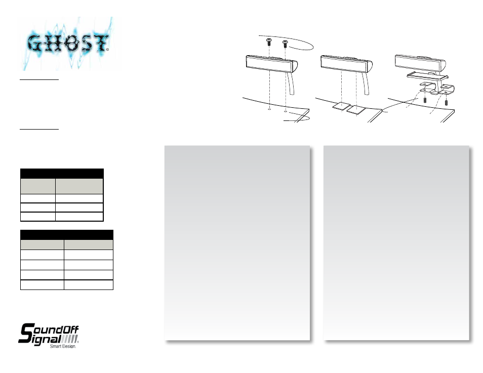
Permanent Mount
Adhesive Mount
Single Edge Mount Bracket
#10 thread forming screws (included)
Hole with #27 drill
Supplied #10-24 3/8” lg. hex
drive set screw
SINGLE MULTI-MOUNT ECE65 CERTIFIED w/ STANDARD LENS
SINGLE LIGHT
EGHSTE1(x)B - Black
EGHSTE1(x)W - White
EGHSTE1(x)C - Chrome
SINGLE MULTI-MOUNT ECE65 CERTIFIED w/ XYLEX LENS
SINGLE LIGHT
EGHSTE1(x)B-EU - Black
EGHSTE1(x)W-EU - White
EGHSTE1(x)C-EU - Chrome