Raptor single surface mount light, Erpt1ssmdb(x) – SoundOff Signal Raptor Surface Mount User Manual
Page 2
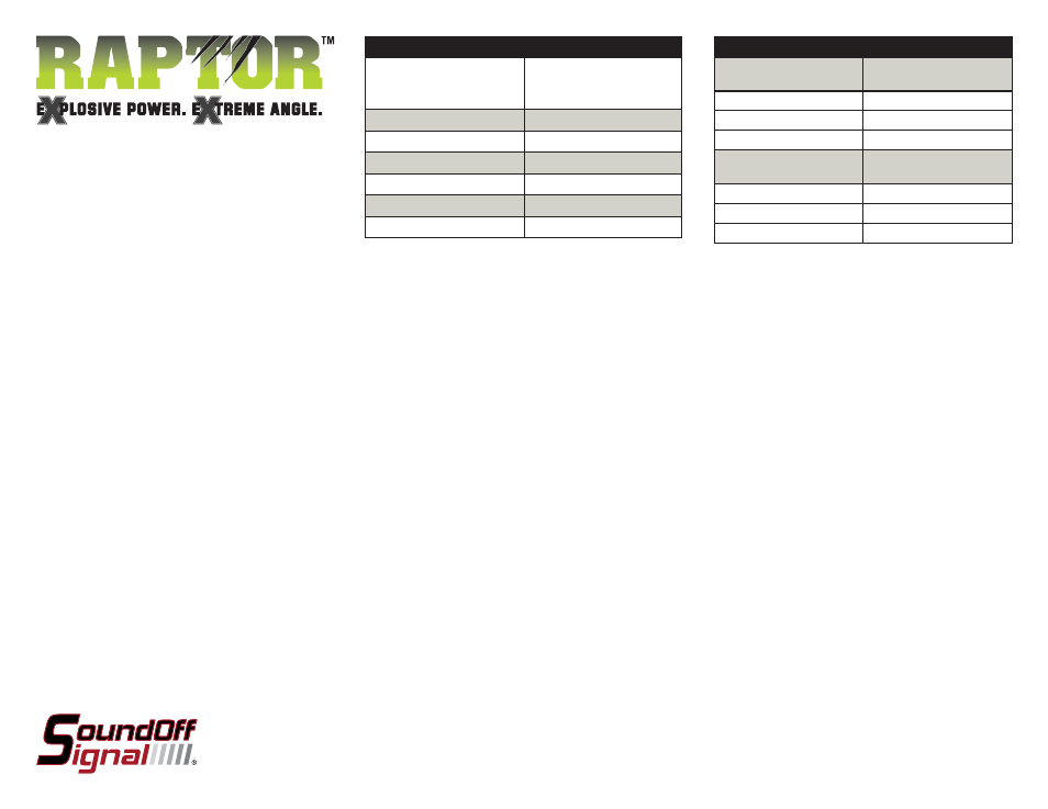
Flash Patterns
Simultaneous Patterns
FPM
(Flashes per Minute)
1. Single
125
2. Double
125
3. Triple
123
Alternating Patterns
FPM
(Flashes per Minute)
4. Single
62
5. Double
62
6. Triple
61
TECHNICAL SPECIFICATIONS
Overall Dimensions:
4.98”(126.6mm)L x
2.75”(70.1mm)W x
1.39”(35.3mm)D
Flash Patterns:
6 fl ash patterns
Input Voltage Range:
10 - 30 Vdc
Current Consumption:
less than 2 amps
# of LEDs:
8 Generation 3 LEDs
Light Sync Technology:
Yes
Operating Temperature:
-40º to +65º C
ERPT1SSMDB(x) 9.09
RAPTOR SINGLE SURFACE
MOUNT LIGHT
ERPT1SSMDB(x)
1 LIGHT
Single Light Operation: Follow the ID Selection steps and set the
RAPTOR to ID#1 if it is not already. NOTE: Use Patterns 1-3.
2 LIGHTS
ALTERNATING: To obtain Alternating patterns, follow the ID
SELECTION steps and set one RAPTOR to ID#1 and the other to
ID#3. Then proceed to the PATTERN SELECTION steps. NOTE: Use
Patterns 4-6.
SIMULTANEOUS: To obtain Simultaneous patterns, follow the ID
SELECTION steps and set both RAPTOR lights to ID#1. Then proceed
to PATTERN SELECTION steps. NOTE: Use Patterns 1-3.
RAPTOR Sync Confi guration Instructions
IMPORTANT! A MAXIMUM OF 4 SINGLE LIGHTS
CAN BE SYNCED TOGETHER
1. Set ID#
a. Identify which pattern and sequence you want and look up ID#
settings at right.
b.
Connections
i. RED:
+12Vdc
ii. WHT: +12Vdc (Note: you will need to disconnect after
power
is
applied)
iii.
BLK:
Ground
c. Apply power to unit
d. Without disconnecting power from unit, disconnect WHT
wire
e. Momentarily connect WHT to Ground to change ID #
i.
Identify ID# by number of sequential fl ashes
ii. Possible ID#s: 1 – 4
f. Disconnect power from unit to get out of ID mode.
2. Set Pattern
a. Reapply power to units.
b. Once all Light Head ID#s are confi gured, make sure all
lights are fl ashing the same pattern
c. Connect corresponding colored wires of all units together:
RED to RED, etc.
d.
Change
Pattern
i.
Momentarily connect WHT wires to Ground
ii. Observe pattern change on all lights connected
e. Insulate all wires by taping with electrical tape
3. Connect Master Switch for Application
a. IMPORTANT! Ensure WHT Pattern/Sync Wires are tied
together