Battery replacement, Servicing, Maximum temperature setting – Powers 470 Series VisuGuard Pressure-Balancing Tempering Valve with LCD Temperature Display User Manual
Page 5
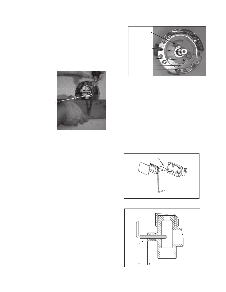
Figure 5 – MAXIMUM TEMPERATURE SETTING
Adj. Stop Screw
Adjustment Stop
Fin
Adjustment Stem
Maximum
Temperature
Stop
5/16
’’ 1/16’’
Temperature
probe
Figure 6
Figure 7
AAA Battery
5
Battery Replacement
n
1. Remove Handle and Cover Plate.
2. Remove thermistor (temperature probe) by loosening small nut
on probe fitting (item 20).
3. Remove electronics enclosure (black) on back of cover plate
(attached with four screws).
4. Once enclosure is removed,
carefully remove lens and elec-
tronic LCD display. Battery and battery holder are located on
back side of display.
5. Remove and replace battery (AAA alkaline).
6. Reverse procedure to reassemble.
Note: See Figure 7 for proper installation of temperature probe.
Servicing
n
1. Remove the dial assembly and handle. See page 3 for rela-
tionship of parts. Close checkstops or upstream valves.
Unscrew four bonnet assembly screws and remove bonnet
assembly by gently pulling on stem. Remove discs, O-rings,
seals, and springs from chamber.
2.
TO REMOVE THE BALANCE CHAMBER, using a balance
chamber extraction tool (Part No. 401-202) is highly recom-
mended. To use the extraction tool, follow instructions below:
a. Insert hooked ends of extraction tool into HOT
and COLD outlet ports of the balance chamber
(see
Figure 4 below).
b. Insert screwdriver down through end of extraction tool.
c. Place a wood or plastic block (do not use metal)
between screwdriver and valve body. Firmly ease
screwdriver away and downward,using wood for added
leverage ascartridge is gradually pulled out.
3. Replace necessary items and reassemble. Place a small
amount of silicone gel on the O-rings only.
4.
CAUTION: Do not pinch cartridge O-rings during assembly.
5. Replace bonnet with new bonnet gasket. Proceed to step 6
to reset maximum temperature setting.
Maximum Temperature Setting
n
6.
MAXIMUM TEMPERATURE SETTING (refer to Figure 5).
This must be set on the job and following any maintenance
or servicing to the valve. Mixer is factory set to pass full
HOT water.
a. Loosen adjustment stop screw (do not remove).
Gradually rotate stem counterclockwise to get desired
maximum water temperature. (Maximum Temperature
Stop will rotate along with the stem when the stem is
rotated.)
b. Once stem has been rotated to desired temperature,
slide adjustment stop clockwise until fin on adjustment
stop touches the maximum temperature stop.
c. While holding adjustment stop in place, tighten adjust-
ment stop screw.
d. Replace handle. Confirm maximum temperature has
been set properly by operating the valve using the handle.
CAUTION: Adjustment stop must be present for proper operation.
Figure 4 – BALANCE CHAMBER REMOVAL
Balance
Chamber
Extraction
Tool