Powers 595 Series 11 Self-Operating Temperature Regulators - Type CD Composition Disc User Manual
Page 6
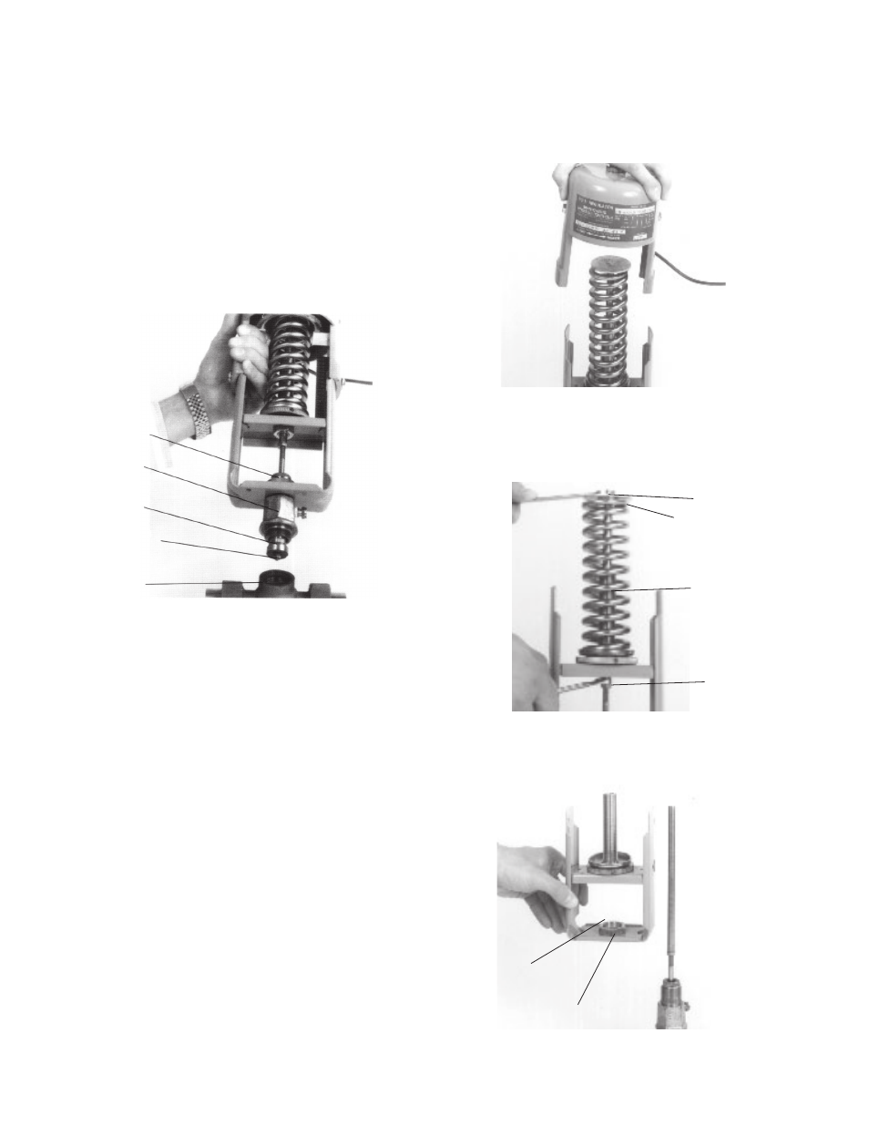
Locknut
9. Lift off yoke and bridge
Yoke and Bridge
3. Figure 7. Remove housing bolts [6] and nuts [7] and tempera-
ture adjustment setting scale [8] and lift off thermal system
[1] (housing, bellows, capillary, and bulb).
Figure 8. Using one 3/8" wrench and one 5/16" wrench, carefully
loosen and remove piston plate assembly [2,3] from the stem
extension [4]. Lift off spring [19].
4.
Figure
9. Use 1-3/8" wrench to unscrew lock nut [11] and lift
off the yoke and bridge assembly [9].
Maintenance
■
Number in brackets [#] refer to part numbers on pp. 10 & 11.
To replace the composition disc only
1. Before disassembly, the bulb must be cooled 30°F (16°C)
below the lowest point on the thermal system range,
and fl ow through the valve must be stopped.
2. Figure 5. Relieve all pressure on the spring by turning adjust-
ing nut assembly [31]fully right to left (clockwise from top).
3. Figure 6. Loosen lock nut [11] with 1-3/8" open end wrench.
Use the 1-3/8" wrench to unscrew bonnet [20] from valve
body [26]. DO NOT ALLOW the regulator top to rotate.
Lift up regulator top.
4. Remove disc retainer nut [25] and replace disc [24].
5. Assemble in reverse order.
To fully disassemble regulator from valve
1. Before disassembly, the bulb must be cooled 30°F (16°C)
below the lowest point on the thermal system range,
and fl ow through the valve must be stopped.
2. Figure 5. Relieve all pressure on the spring by turning adjust-
ing nut assembly [31]fully right to left (clockwise from top).
Body
6. Lift off Regulator from valve
Lock Nut
Bonnet
Disc
Disc Retainer
Nut
Piston Plate Assembly
3/8" Nut
Spring
5/16" Nut
8. Remove Piston Plate/Spring
7. Remove Housing and Thermal System
6