Installation, Product identifi cation – Powers 595 Series 11 Self-Operating Temperature Regulators - Type CD Composition Disc User Manual
Page 5
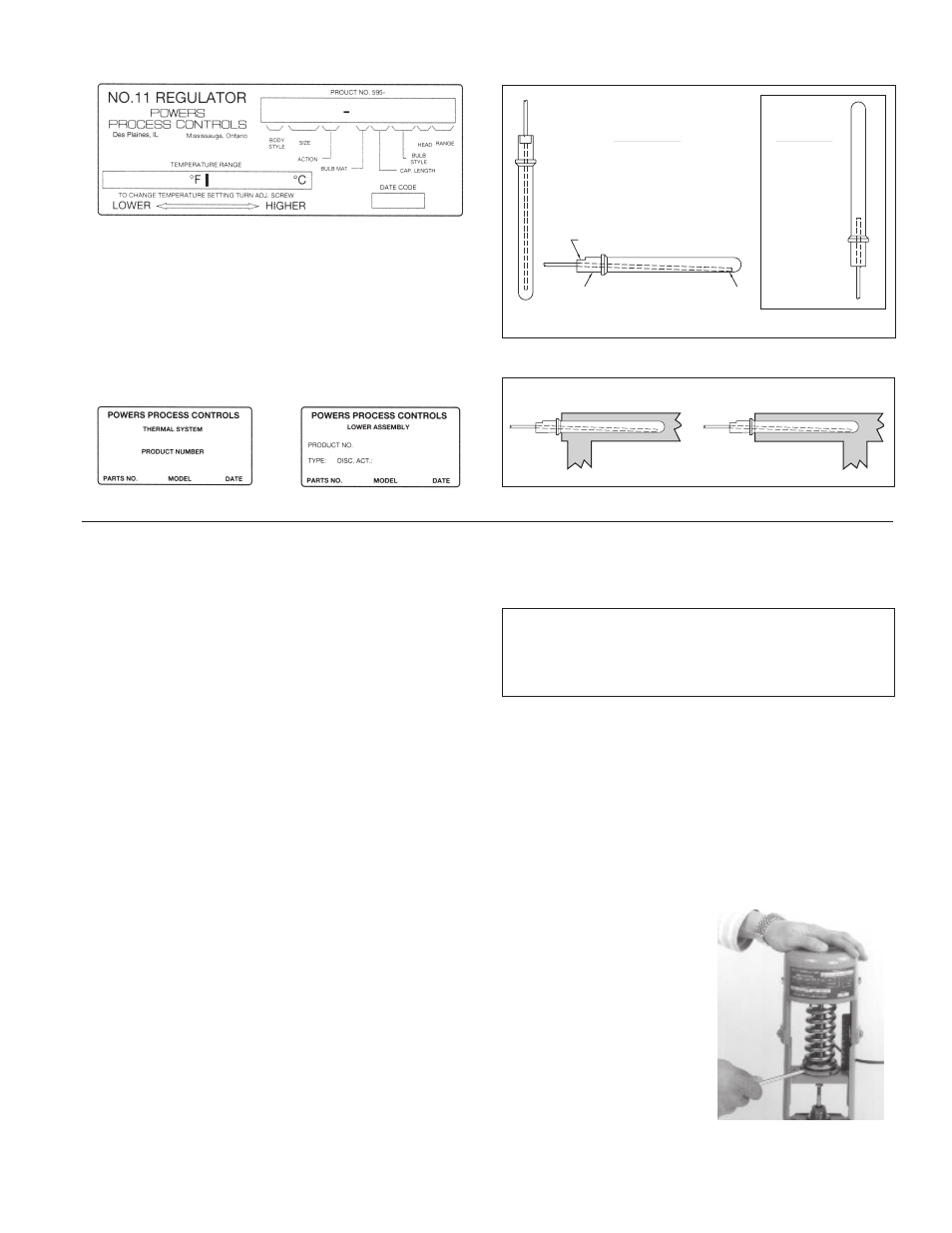
A red label should be on the front face of the thermal system.
Figure 1. This label contains information required to properly
maintain, service and order parts for this product. If there is no
label, look for a white label on the inside of the thermal system
legs (Figure 2A) or the valve body vertical yoke (Figure 2B)
When replacing the original thermal assembly or valve body,
secure the old red label onto the valve or thermal system or ink
the number onto the body.
Installation
■
Tools
Needed
• Straight slot screwdriver
• 5/16" open end wrench
• 3/8" open end wrench
• 7/16" open end wrench
• 1-3/8" open end wrench
• Pliers
Position Valve
1. To insure proper system operation, thoroughly fl ush all piping
and valves to rid them of all scale, dirt and debris.
2. Select valve location with suffi cient clearance to allow
maintenance. Install valve in line. The direction of the arrows
on the valve body must match the direction of the water or
steam fl ow.
For best results, we recommend installing the valve in a
horizontal line, and in the upright position with bellows head
above valve. The valve may also be installed in any position
within 90° of upright.
Install Bulb
3. Figure 3a shows proper bulb orientation. Figure 3b shows the
special bulb needed for upwards vertcial positioning.
4. Figure 4. For any position, fully immerse the bulb in the fl ow
of the medium.
These instructions are for D style bulbs - for installation of other
styles, refer to tag attached to bulb.
5. Without a well: Remove bushing from the bulb and screw it
into the tank. Insert the thermostatic bulb through the bush-
ing and tighten the union nut.
With a well: Do not use bushing. Screw well into tank, insert
bulb directly into well, and tighten union nut.
WORD "TOP" ON FLAT SURFACE FACING UP
HEAD
END
TOP
Standard Bulb
Downward Vertical (left)
or
Horizontal (below)
Only
Special Bulb
Upward Vertical
Only (right)
1. Product Label
2
B
. Valve Body Label
2
A
. Thermal System Label
3
A
. Bulb Orientation
3
B
. Special Bulb
Correct: Bulb in flow of medium
Incorrect: Bulb not in flow of medium
4. Bulb Positions
Product Identifi cation
■
Adjust Capillary Tubing
6. Coil the extra capillary, and position away from regulator
operation where it is subjected to room temperature only.
WARNING: DO NOT kink, cut, sever or fi le the tubing.
DO NOT disconnect tubing from bulb or bellows assembly.
This can render the thermal system inoperable and result in
severe process overheating.
Adjust set point
All regulators are factory set to control near mid-range
operating temperature.
7. When adjusting the set point, make certain the heating
medium is fl owing through the valve and is at the operating
pressure of the system.
8. Figure 5. Make all set point temperature changes by inserting
the temperature adjustment rod into one of the holes of the
adjusting nut assembly. (Use the temperature adjustment
setting scale only for reference)
To Raise the set point:
Turn rod left to right
(counterclockwise
from top).
To Lower the set point:
Turn rod right to left
(clockwise from top).
5. Adjusting Set Point
5