Center of gravity, Control throws – E-flite Advance 25e User Manual
Page 30
30
E-flite Advance 25e ARF Assembly Manual
Center of Gravity
Required parts
Assembled airframe
Required Tools and Adhesives
Felt-tipped pen
Ruler
Phillips screwdriver: #2
Balancing stand (optional)
An important part of preparing the aircraft for flight is
properly balancing the model.
CAUTION: Do not inadvertently skip this step or
property damage and injury could occur.
1. Assemble your model in preparation for flight,
making sure the wing is on securely and the motor
battery is installed as instructed in this manual.
2. The recommended Center of Gravity (CG)
location for your model is 3 to 3
1
/
2
inches (76 to
89mm) back from the leading edge of the wing
as shown with the battery pack installed. Mark the
location of the CG on the top of the wing with a
felt-tipped pen.
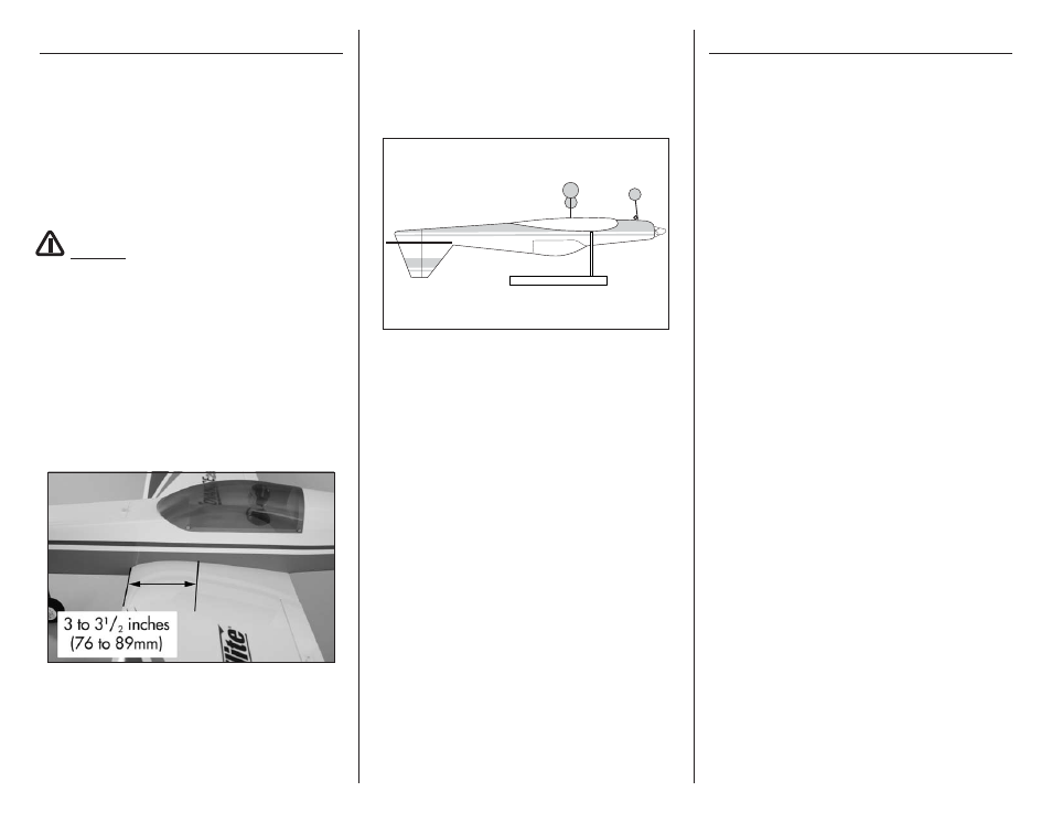
3. When balancing your model, support the plane
inverted at the marks made on the top of the wing
with your fingers or a commercially available
balancing stand. This is the correct balance point
for your model. Make sure your model is assembled
and ready for flight before balancing.
Balancing Stand
Adjust the motor battery as necessary so the model is
level or slightly nose down. This is the correct balance
point for your model. You should find the CG to be
very close with the battery installed as shown in this
manual. Mark the location of the battery on the battery
tray using a felt-tipped pen so it can be returned to this
position if it is removed from your model.
After the first flights, the CG position can be adjusted
for your personal preference.
Control Throws
1. Turn on the transmitter and receiver of your
model. Check the movement of the rudder using
the transmitter. When the stick is moved right, the
rudder should also move right. Reverse the direction
of the servo at the transmitter if necessary.
2. Check the movement of the elevator with the
radio system. Moving the elevator stick toward
the bottom of the transmitter makes the airplane
elevator move up.
3. Check the movement of the ailerons with the
radio system. Moving the aileron stick right makes
the right aileron move up and the left aileron
move down.
4. Use a ruler to adjust the throw of the elevator,
ailerons and rudder. Adjust the position of
the pushrod at the control horn to achieve the
following measurements when moving the sticks to
their endpoints.
Elevator high Rate (100%) (20% Exponential)
Up
19/32-inch (15mm)
23 degrees
Down
23/32-inch (18mm)
25 degrees
Elevator Low Rate (15% Exponential)
Up
11/32-inch (8.5mm)
13 degrees
Down
13/32-inch (10.5mm) 15 degrees
Aileron high Rate (100%) (20% Exponential)
Up
17/32-inch (13.5mm) 25 degrees
Down
17/32-inch (13.5mm) 25 degrees
Aileron Low Rate (15% Exponential)
Up
13/32-inch (10.5mm) 19 degrees
Down
13/32-inch (10.5mm) 19 degrees