Rudder and elevator linkage installation – E-flite Advance 25e User Manual
Page 25
25
E-flite Advance 25e ARF Assembly Manual
7. Flex the elevator through its range of motion
a number of times to break in the hinges. This
will reduce the initial load on the servo for
your first flights.
8. Repeat Steps 1 through 7 to attach the rudder to
the fin and fuselage using three CA hinges.
Rudder and Elevator
Linkage Installation
Required parts
Fuselage assembly Transmitter
Silicone tubing
Nylon clevis (2)
Nylon control horn with backplate (2)
2mm x 12mm machine screw (4)
Pushrod wire, 24-inch (610mm) (2)
Required Tools and Adhesives
Pin vise
Drill bit: 5/64-inch (2mm)
Pliers
Felt-tipped pen
Thin CA
Hobby knife with #11 blade
Ruler
Phillips screwdriver: #1
Side cutter
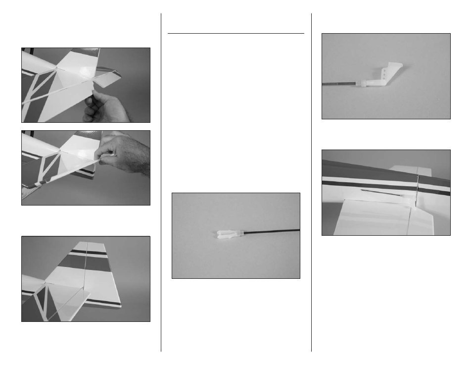
1. Use a hobby knife with a #11 blade to cut
a 1/4-inch (6mm) piece from the silicone tube.
Slide the small piece of tubing on a nylon clevis.
Thread the clevis 12-turns on a 24-inch (610mm)
threaded pushrod wire. This will provide enough
thread in the clevis to be secure and allow for
adjustment of the linkage.
2. Attach the clevis to the outer hole on the nylon
control horn.
3. Slide the pushrod in the preinstalled elevator
pushrod tube.