Nose gear installation – E-flite Advance 25e User Manual
Page 13
13
E-flite Advance 25e ARF Assembly Manual
Nose Gear Installation
Required parts
Fuselage assembly Nose gear mount
Nylon clevis
Silicone tubing
Nose gear wire
Wheel, 2-inch (51mm)
Nylon spacer
3mm x 15mm machine screw (4)
Steering arm with screw
Wheel collar with screw
Pushrod wire, 24-inch (610mm)
Nylon tube, 11
7
/
8
-inch (302mm)
Required Tools and Adhesives
Ruler
Medium grit sandpaper
Threadlock
Phillips screwdriver: #1
Felt-tipped pen
Hobby knife with #11 blade
Pliers
Side cutter
Medium CA
Flat file
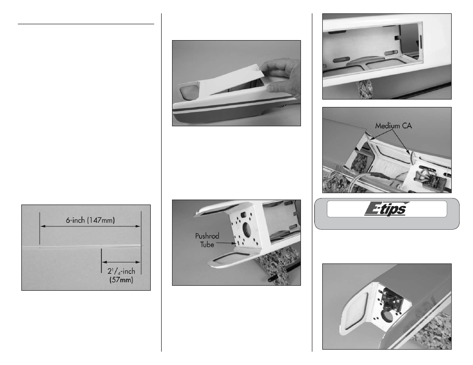
1. Use medium grit sandpaper to lightly sand a
1/4-inch (6mm) wide section of the 11
7
/
8
-inch
(302mm) pushrod tube. This provides a surface for
the CA to bond to when the pushrod is glued in the
fuselage. Use the photo to locate the areas that are
2
1
/
4
-inch (57mm) and 6-inches (147mm) from the
end of the tube.
2. Remove the battery cover by rotating the knob on
the cover 90-degrees. Lift the cover and set it aside
in a safe location.
3. Slide the pushrod tube into the fuselage
through the oval hole in the firewall with the
2
1
/
4
-inch (57mm) sanded end first. The tube
will be routed up through the battery tray, then
through the hole in the former near the servo
tray. With the end of the tube flush with the
firewall, use medium CA to glue the tube where
it crosses the formers inside the fuselage.
Always use threadlock on metal-to-metal fasteners.
4. Attach the nose gear mount to the firewall using
four 3mm x 15mm machine screws and a #1
Phillips screwdriver.