Electrical installation – Banner DUO-TOUCH Run Bar with STB Buttons User Manual
Page 6
Separation Distance (D
s
) Calculation
The following example illustrates the use of the formula to calculate separation distance for a part-revolution clutch
machine. This example uses 0.50 seconds as a typical value for T
s
and 0.02 seconds for T
h
:
K = 63" per second,
T
s
= 0.50 seconds (measured by a stop-time measuring device)
T
r
= 0.035 seconds
T
h
= 0.02 seconds
D
s
= K × (T
s
+ T
r
+ T
h
)
= 63" (0.50 + 0.035 + 0.02)
= 35"
In this example, both hand controls must be located no closer than 36" from the nearest hazard point.
Electrical Installation
Electrical installation of hand controls, the DUO-TOUCH SG Safety Module, and the interconnection to the machine control
must be made by qualified personnel and must comply with NEC (National Electrical Code), ANSI/NFPA 79 or IEC 60204-1,
and all applicable local standards.
It is not possible to give exact wiring instructions for a Safety Module that interfaces to a multitude of machine control
configurations. The following guidelines are general in nature.
CAUTION: Disconnect Power Before Wiring
Before making any wire connections, make certain all power is disconnected from the Safety
Module and the machine to be controlled.
Electrical installation of hand controls, the DUO-TOUCH SG Safety Module, and the interconnection to
the machine control must be made by qualified personnel and must comply with NEC (National
Electrical Code), ANSI/NFPA79 or IEC60204-1, and all applicable local standards.
Dangerous voltages may be present along the Safety Module wiring barriers whenever power to the
machine control elements is On. Exercise extreme caution whenever machine control power is
or may be present. Always disconnect power to the machine control elements before opening
the enclosure housing of the Safety Module.
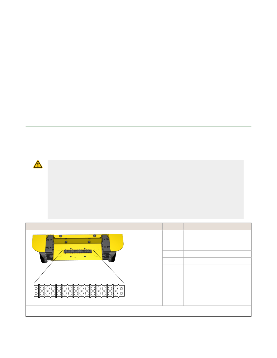
Terminal
Connection
1
2
3
4
5
6
7
8
9
10
11
12
13
14
Terminal
Figure 4. Terminal Strip Connections
1
STB 1 N.O. (black)
2
STB 1 COM (yellow, if used)
3
STB 1 N.C. (white)
4
STB +24V dc (brown)
5
STB 0V dc (blue)
6
STB 2 N.O. (black)
7
STB 2 COM (yellow, if used)
8
STB 2 N.C. (white)
NOTE: The STBVP6 hand control buttons are pre-wired to terminals 1, 3, 4, 5, 6, and 8. Terminals 2 and 7 are reserved for use of
STBVR81 buttons.
DUO-TOUCH Run Bar with STB Buttons
6
www.bannerengineering.com - tel: 763-544-3164
Datasheet 131634_web Rev.
E