System introduction, Introduction — overview, 1 system description – Banner EZ-SCREEN Safety Light Curtain Systems User Manual
Page 4
page
4
Banner Engineering Corp.
•
Minneapolis, MN U.S.A.
www.bannerengineering.com • Tel: 763.544.3164
System Introduction
EZ-SCREEN Grid
Instruction Manual
1. Introduction — Overview
1.1 System Description
The Banner EZ-SCREEN™ Grid System is an optically synchronized,
microprocessor-controlled, opposed-mode optoelectronic “light grid.” This
economical two-part system consists of an emitter and receiver. The system
requires no external controller or sync wire between the emitter and receiver; the
microprocessors are located within the receiver. The receiver has two solid-state
safety outputs to control 24V dc loads. If an ac-powered MPCE or other load is
required, an accessory interface module may be used to convert the EZ-SCREEN
dc outputs to isolated, forced-guided relay contacts. (See Section 2.2 and Figures
3-17 and 3-18 for more information.)
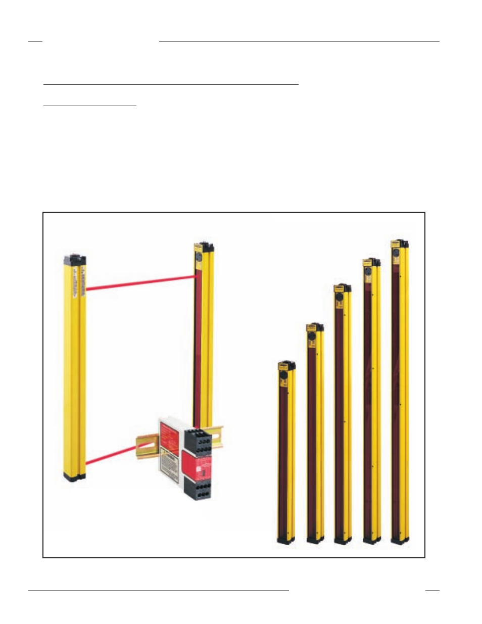
Figure 1-1. EZ-SCREEN Models
SG..2-500
2 beams
500 mm (19.7")
Spacing
SG..3-400
3 beams
400 mm (15.7") Spacing
SG..3-533
3 beams
533 mm (21") Spacing
SG..4-300
4 beams
300 mm (11.8") Spacing
SG..2-584
2 beams
584 mm (23") Spacing
Each EZ-SCREEN Grid System
needs only an emitter and a receiver.
Optional Interface Module is available for
switching ac or larger dc loads. (See
Section 2.2 for more information on the
Interface Module.)
See pages 57-58 for quick-disconnect options.
Dots on
housing
indicate beam
placement
(dot size is
exaggerated
for visibility).