Specifications, 6 dimensions, Ez-screen grid – Banner EZ-SCREEN Safety Light Curtain Systems User Manual
Page 15: Model beam spacing l4 housing length, Distance between brackets l1 l2 l3
page
15
Banner Engineering Corp.
•
Minneapolis, MN U.S.A.
www.bannerengineering.com • Tel: 763.544.3164
Specifications
EZ-SCREEN Grid
Instruction Manual
BEAMS
1
2
R
E
S
E
T
S
T
A
T
U
S
BEAMS
1
2
R
E
S
E
T
S
T
A
T
U
S
EZ-SCREEN Grid
BANNER ENGINEERING CORP., USA
888.373.6767
EZ-SCREEN Grid
BANNER ENGINEERING CORP., USA
888.373.6767
107.0 mm
(4.21")
26 mm
(1.02")
L1
L2
25 mm
(1.0")
60.0 mm
(2.36")
74.2 mm
(2.92")
L3
16.7 mm
(0.66")
See Notes
Below
12.5 mm (0.50")
Minimum Bend Radius
L4
52 mm
(2.0")
55 mm
(2.1")
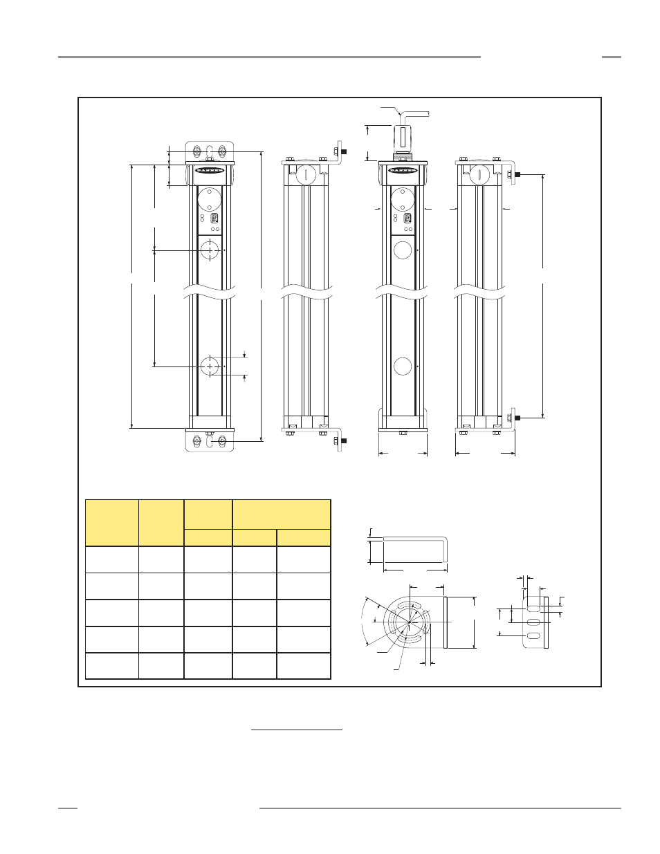
Figure 2-1. EZ-SCREEN dimensions (standard end-cap brackets shown) and EZA-MBK-1 mounting bracket dimensions
Model
Beam
Spacing
L4
Housing
Length
SG..2-584
584 mm
(23")
768 mm
(30.8")
SG..3-533
533 mm
(21")
1251 mm
(49.2")
SG..2-500
500 mm
(19.7")
684 mm
(26.9")
SG..3-400
400 mm
(15.7")
984 mm
(38.7")
Distance Between
Brackets
L1
L2
L3
1017 mm
(40.1")
717 mm
(28.2")
1284 mm
(50.6")
802 mm
(31.6")
743 mm
(29.3")
1226 mm
(48.3")
659 mm
(25.9")
959 mm
(37.8")
SG..4-300
300 mm
(11.8")
1084 mm
(42.7")
1117 mm
(44")
1059 mm
(41.7")
74.2 mm
(2.92")
4.2 mm
(0.17")
25.0 mm
(0.98")
60.0 mm
(2.36")
40 mm
(1.57")
ø 32.0 mm
(1.26")
ø 43.0 mm
(1.69")
2x 30.0°
2x 60.0°
4x 5.8 mm
(0.23")
5.0 mm
(0.20")
15.0 mm
(0.59")
3x 7.0 mm
(0.28")
15.8 mm
(0.62")
31.5 mm
(1.24")
CL
CL
EZ-SCREEN
Standard Mounting Bracket
EZA-MBK-1
See page 11 for information
about other accessory brackets.
NOTE: QD models have identical mounting dimensions.
Allow additional height for QD fitting:
69 mm (2.7” for emitters (3- or 5-pin)
89 mm (3.5”) for receivers (8-pin)
2.6 Dimensions
Figure 2-1 shows the dimensions of the five basic configurations, including the
placement of the individual beams. Note that beam spacing varies from model to
model; the beam spacing selected depends on the specific standard(s) being
satisfied for the individual application.