Installation and alignment – Banner EZ-SCREEN Safety Light Curtain Systems User Manual
Page 29
page
29
Banner Engineering Corp.
•
Minneapolis, MN U.S.A.
www.bannerengineering.com • Tel: 763.544.3164
Installation and Alignment
EZ-SCREEN Grid
Instruction Manual
4) Route the wires or cabling through the bracket (if necessary) and the wiring
chamber end cap. Remove outer cable insulation as necessary (approximately
1" to 2") and strip the individual wire insulation approximately 7 mm (0.25");
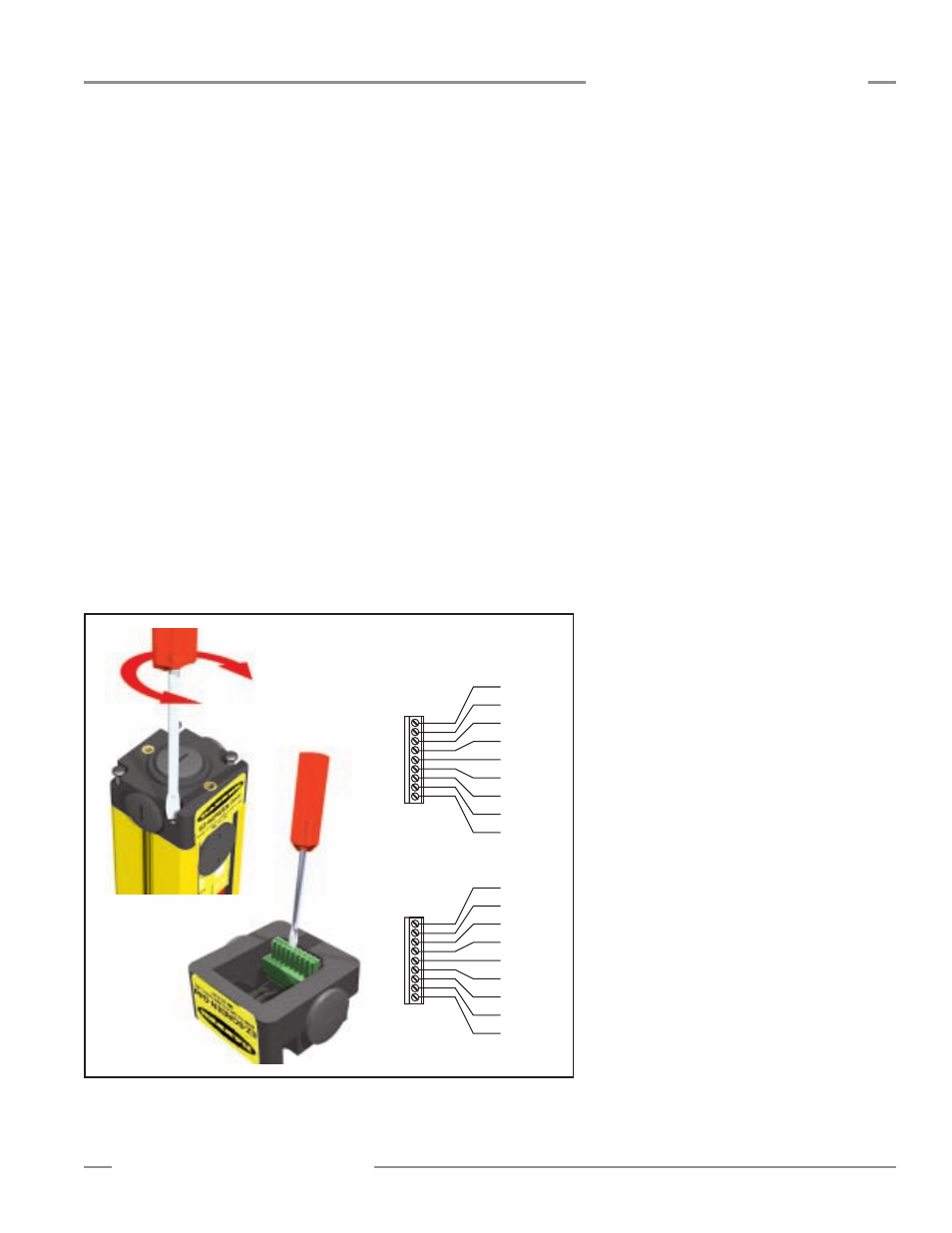
make connections to terminals as indicated in Figure 3-11. Torque the terminal
screws to 0.22 to 0.25 N m (1.9 to 2.2 in. lbs.) recommended torque.
Emitter: If Test input will be used, connect the wires at the emitter terminal
block and temporarily connect the other ends of the wires to each other (but not
to an external contact at this time).
If Test input will not be used, leave the factory jumper in place.
Terminals 7, 8 and 9 are provided to allow convenient power connection (24V
dc, 2 amp max.) to another EZ-SCREEN emitter. These terminals are a direct
connection to terminals 3, 2 and 1 respectively. A 24V dc, 2-amp external fuse
is recommended to limit the current on terminal 7.
Receiver: While all wires will not be connected to the machine control circuits
at this time, connect the receiver end of all wires to their connections on the
receiver terminal block.
If EDM will not be used (no monitoring), jumper terminals 6 and 7. (A jumper
wire is supplied in the hardware kit.)
If 2-channel monitoring will be used, connect the wires to receiver terminals 6
and 7 and temporarily connect the other ends of the wires to each other (but
not to the machine at this time).
If 1-channel monitoring will be used, add a jumper between terminals 6 and 7
for the initial checkout. Final EDM wiring must be completed later.
5) Recheck the wires to be sure connections
are accurate and that wiring complies with
applicable (international, national and
local) codes.
6) Snap the terminal block back into the end
cap. Replace the end cap on the end of
the housing, being careful to align the end
cap terminals with the corresponding
terminals in the housing. When the end
cap is screwed back into place on the
housing, the two terminal block sections
will automatically connect.
Reset Switch Hookup
Emitter
Terminal
Block
PE
1
9
dc COM
+24V dc
TEST2
TEST1
(Not Used)
+24V dc
dc COM
PE
Receiver
Terminal
Block
PE
1
9
dc COM
+24V dc
(Not Used)
RESET
EDM1
EDM2
OSSD1
OSSD2
Figure 3-11. Making connections to the sensor terminal blocks
Connect the external Reset switch to the
Reset terminal on the receiver terminal block
and to 24V dc (see Figures 3-16, 3-17 and
3-18).
Configuring the System for Initial Checkout
Verify that the System is set to the factory
presets for initial checkout and optical
alignment. (Factory presets are for Latch
Output, 2-Channel EDM, and Scan Code 1;
receiver terminals 6 and 7 should be
connected, as described in step 4 above.)
See Figure 4-1.