System components and specifications, 1 models available, 2 accessories – Banner EZ-SCREEN Safety Light Curtain Systems User Manual
Page 10
page
10
Banner Engineering Corp.
•
Minneapolis, MN U.S.A.
www.bannerengineering.com • Tel: 763.544.3164
System Components and Specifications
EZ-SCREEN Grid
Instruction Manual
2. System Components and Specifications
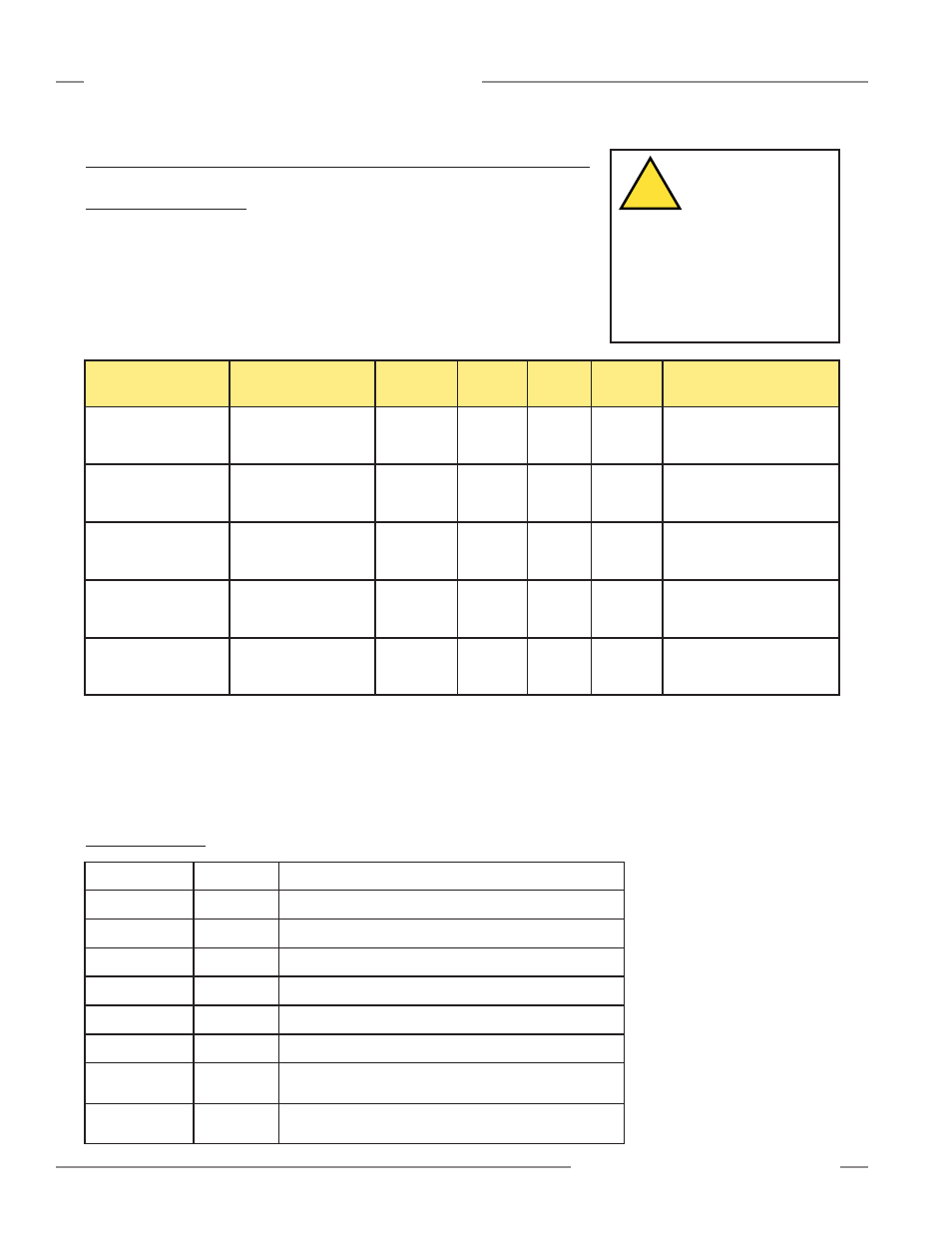
2.1 Models Available
Banner EZ-SCREEN Grid components may be purchased individually or in kits.
Kits (as indicated below) include one emitter, one receiver, a keyed reset switch,
two cable glands, two spanner wrenches, a test piece, and standard mounting
hardware for both sensors. When purchased separately, the emitter and receiver
each include mounting hardware for one sensor, one cable gland, a test piece,
and a spanner wrench. Keyed reset switches are also available separately.
Short-Range Models*
(0.8 m - 20 m)
Long-Range Models*
(15 m - 70 m)
Overall
Length
Number
of Beams
SGE2-584 Emitter
SGR2-584 Receiver
SGP2-584 Kit
SGXLE2-584 Emitter
SGR2-584 Receiver
SGXLP2-584 Kit
768 mm
(30.2")
2
SGE3-533 Emitter
SGR3-533 Receiver
SGP3-533 Kit
SGXLE3-533 Emitter
SGR3-533 Receiver
SGXLP3-533 Kit
1251 mm
(49.3")
3
SGE2-500 Emitter
SGR2-500 Receiver
SGP2-500 Kit
SGXLE2-500 Emitter
SGR2-500 Receiver
SGXLP2-500 Kit
684 mm
(26.9")
2
SGE3-400 Emitter
SGR3-400 Receiver
SGP3-400 Kit
SGXLE3-400 Emitter
SGR3-400 Receiver
SGXLP3-400 Kit
984 mm
(38.7")
3
SGE4-300 Emitter
SGR4-300 Receiver
SGP4-300 Kit
SGXLE4-300 Emitter
SGR4-300 Receiver
SGXLP4-300 Kit
1084 mm
(42.7")
4
300 mm
(11.8")
400 mm
(15.7")
500 mm
(19.7")
533 mm
(21")
584 mm
(23")
Beam
Spacing
900 mm
(35.4")
800 mm
(31.5")
500 mm
(19.7")
1066 mm
(42")
584 mm
(23")
Protected
Height
EN 999
ANSI/RIA R15.06
ANSI B11
EN 999
EN 999
ANSI/RIA R15.06
ANSI B11
ANSI/RIA R15.06
ANSI B11
Application Standard
2.2 Accessories
LAT-1
52150
Laser Alignment Tool with adapter clip
EZA-LAT-1
66027
Clip-on retroreflective target
BT-1
26809
Beam Tracker
SI-QS-CG13
48564
Pg13.5 cable gland
SI-QM-13
48559
Adapter, 1/2" NPT to Pg13.5
Interface Modules provide
isolated safety contacts for a
Primary Safety Device (the
EZ-SCREEN Grid System).
See data sheet p/n 62822 for
more information.
* Hard-wired models only are listed. Add the suffixes listed below for quick-disconnect models; see pages 57-58
for more information.
Emitter suffix Q3: 3-pin Mini-style QD, Test input jumpered
Emitter suffix Q5: 5-pin Mini-style QD, Test input available
Receiver suffix Q8: 8-pin Mini-style QD
BRT-THG-2-100
26620
50 mm (2") wide reflective tape, 2.5 m (100") long
SI-QM-13-M20
66579
Adapter, M20 to Pg13.5
CAUTION . . .
Proper Model
Selection
Ensure proper
selection of emitter models,
with respect to range (operating
distance) between emitter and
receiver, to minimize the
possibility of optical short circuits
(see Section 3.3.4).
!
IM-T-9A
61425
Interface Module (3 normally open redundant-output
contacts)
IM-T-11A
61424
Interface Module (2 normally open redundant-output
contacts plus 1 normally closed auxiliary output contact)