Installation and alignment, Warning, Caution – Banner EZ-SCREEN Safety Light Curtain Systems User Manual
Page 39
page
39
Banner Engineering Corp.
•
Minneapolis, MN U.S.A.
www.bannerengineering.com • Tel: 763.544.3164
Installation and Alignment
EZ-SCREEN Grid
Instruction Manual
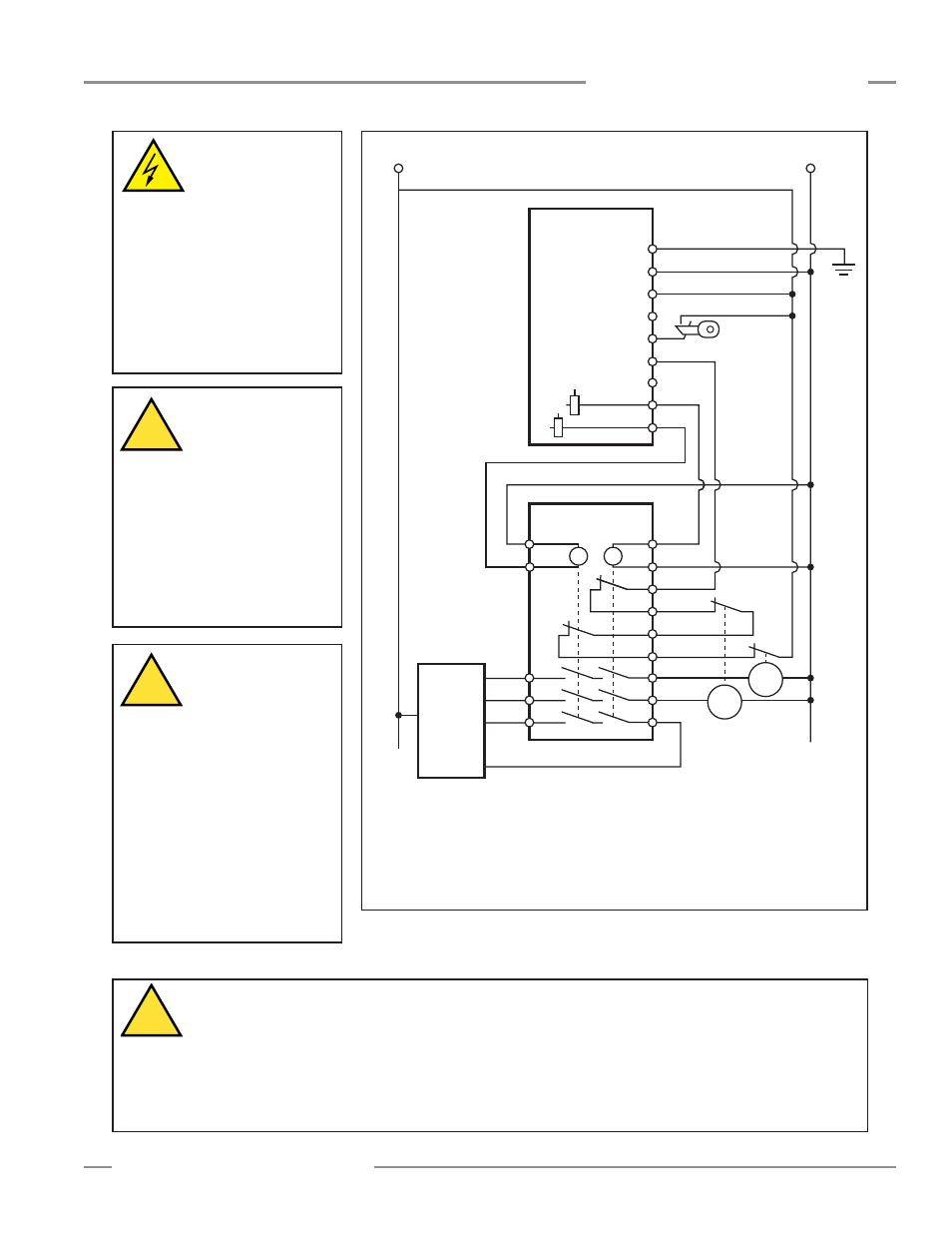
+24V dc
0V dc
Reset
PE 1
dc Com 2
+24V dc 3
(Not Used) 4
RESET 5
EDM1 6
EDM2 7
OSSD1 8
OSSD2 9
S1
S2
Y1
Y2
Y3
Y4
14
24
34
13
23
33
S4
S3
EZ-SCREEN
Receiver
(1)
IM-T-9A
+
+
K2
K1
MPCE
2
Feedback (optional)
MPCE
1
Machine
Control
(2)
* Installation of transient suppressors
across the coils of MPCE1 and MPCE2 is
recommended (see Warning).
+
+
*
*
1) See Section 3.5 for
more information on
Reset input and hookup.
2) See Section 3.7.3 for
information on EDM
input and hookup.
Figure 3-18. EZ-SCREEN receiver generic hookup – interface module
(1-channel EDM, key reset)
WARNING . . .
Proper Wiring
The generalized wiring
configurations shown are provided
only to illustrate the importance of
proper installation.
The proper wiring of the EZ-
SCREEN Grid System to any
particular machine is solely the
responsibility of the installer and
end user.
!
CAUTION. . .
Shock Hazard
Always disconnect all
power from the EZ-SCREEN System
and the guarded machine before
making any connections or
replacing any component. Use
extreme caution to avoid electrical
shock at all times.
Serious bodily injury or death
could result.
WARNING . . .
Use of Transient
Suppressors
If transient suppressors are used,
they MUST be installed across the
coils of the machine control
elements. NEVER install
suppressors directly across the
contacts of the IM-T-..A Module! It
is possible for suppressors to fail as
a short circuit. If installed directly
across the contacts of the IM-T-..A
Module, a short-circuited
suppressor will create an unsafe
condition.
!
WARNING . . .
OSSD Interfacing
To ensure proper operation, the EZ-SCREEN OSSD output parameters and machine input parameters must be
considered when interfacing the EZ-SCREEN solid-state OSSD outputs to machine inputs.
Machine Control circuitry must be designed so that the maximum load resistance value is not exceeded and that the
maximum specified OSSD OFF-state voltage does not result in an ON condition.
Failure to properly interface the OSSD outputs to the guarded machine could result in serious bodily injury or death.
!