Diagnosis of digital timer, 8 diagnosis, Digital timer – Metrohm 765 Dosimat User Manual
Page 29: 8 diagnosis of digital timer
3.2 Diagnosis
765 Dosimat
25
1.
Prepare instrument for diagnostic test (see chap. 3.2.3).
2.
Connect voltmeter, DVM or recorder by means of cable 3.980.3170 to location A
(do not switch off the unit).
Plug A Pin 21 (0...+1 V)
Plug A Pin 11 (ground)
3.
<3>
analog output
4.
V-out = 0.000 V
Measuring instrument reads 0 V (tolerance
±
6 mV). Take also into account the tolerance of the measuring
instrument!
5.
V-out = 1.000 V
Measuring instrument reads +1.000 V (tolerance
±
6 mV + tolerance of point 4.)
6.
V-ramp 1...2
In this test sequence the Dosimat produces at the analog output a triangle voltage. Two different rising or fal-
ling times can be selected:
1:
rising or falling time = 48 ms (reserved for the service engineer)
2:
rising or falling time = 40 s
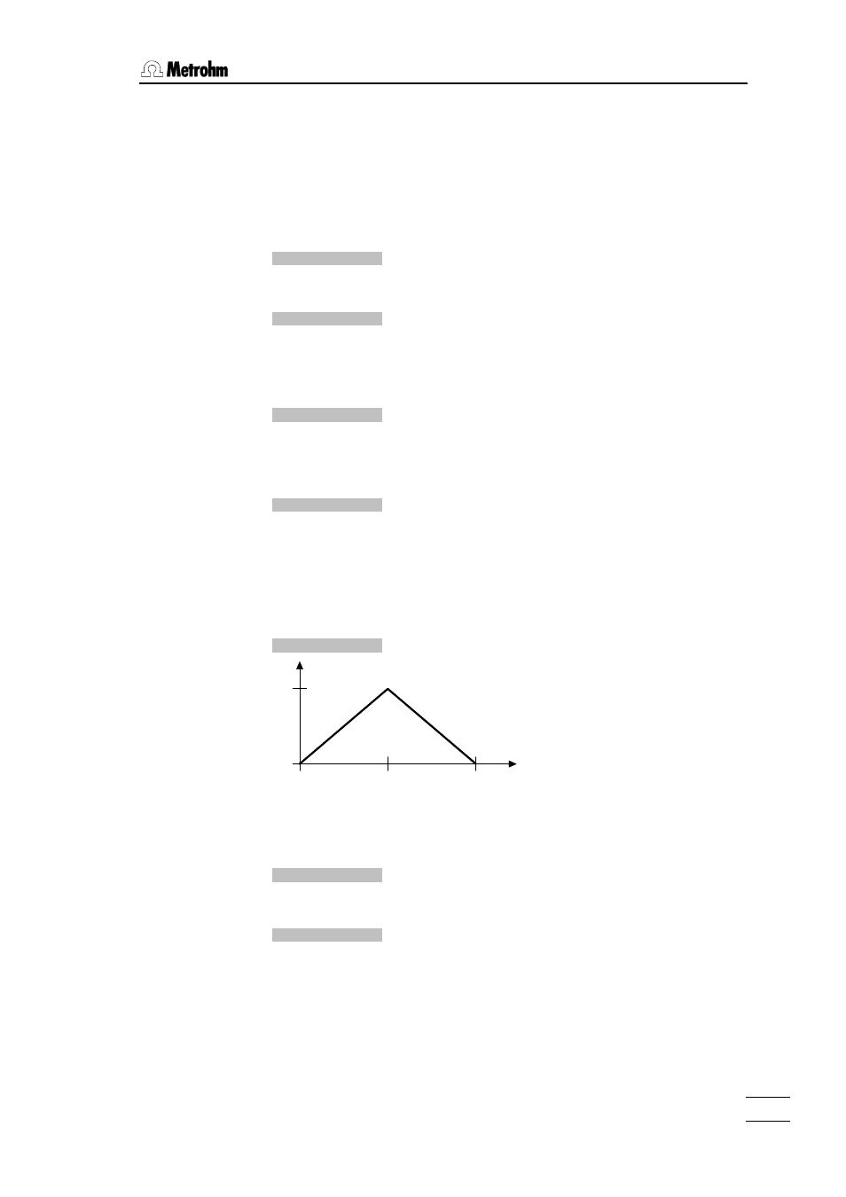
7.
<2>,
V-ramp = 40s ↑/↓
U
out
[V]
80
1
40
0
t [s]
Within the first 40 s the voltage rises linear.
Within the second 40 s the voltage falls linear.
When terminated the display shows:
V-ramp = 1...2
8.
diagn. key 0...9
9.
Remove cable and measuring instrument.
3.2.8 Diagnosis of digital timer
The digital timer is that part of the electronic circuit in the dosimat which is responsable
for the digital spindle speed rate.