Installation instructions – Brandmotion 1009-9517 User Manual
Page 14
INSTALLATION INSTRUCTIONS
1009-9000-00
14 of 18
9 August 2011
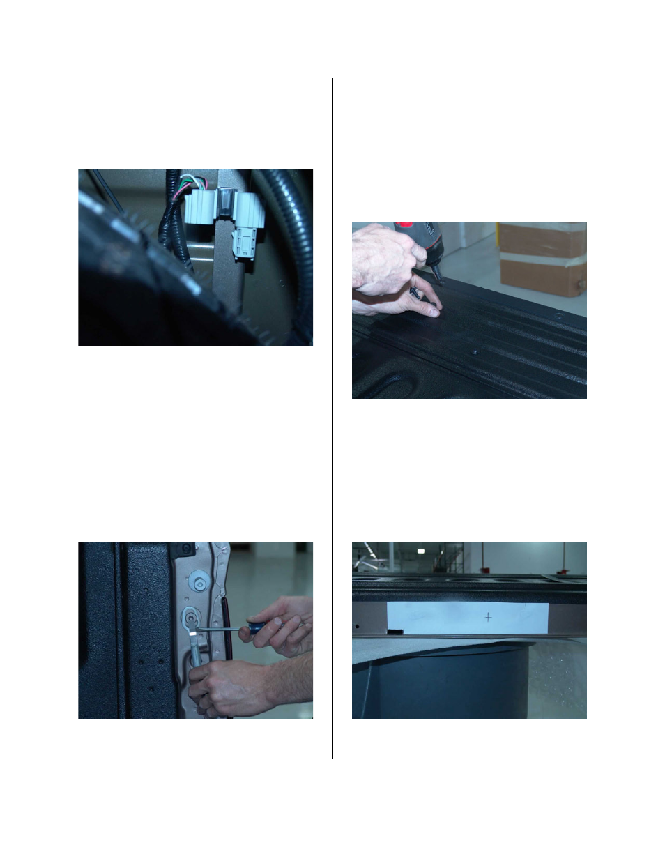
40. Use the retention clip on the bridge
connector at the end of the chassis wiring
harness to attach the connector to the
frame rail of the bed. Tuck the coil of excess
harness above the spare tire. (Figure 28)
Figure 28
41. Set up a work area for the endgate after
removal. This area should be well protected
so the endgate paint does not receive any
damage.
42. Unhook both endgate support straps by
inserting a flat head pocket screwdriver
between the locking tab and strap mount.
Lift the locking tab away from the strap
mount with the screwdriver while sliding the
endgate strap upwards. The endgate strap
hanger can now be removed from the
mount. (Figure 29)
Figure 29
43. Open the endgate about ten degrees and lift
the right side of the endgate off of the pin.
Then slide the endgate to the right to
remove, being careful not to damage the
paint. Note: The endgate removal and
installation will take two people to perform.
44. Remove the handle access panel on the
inside of the endgate using a T30 Torx
driver. (Figure 30)
Figure 30
45. Apply the supplied template to the endgate.
An existing small rectangular hole in the
center of the endgate will match up with the
left side of the template. Center punch the
endgate at the “X” on the template, then
remove the template from the endgate.
(Figure 31)
Figure 31