Pc-2200 – Bowers Group Advanced Electronic/Air Column PC-2200 User Manual
Page 19
PC-2200
BOWERS METROLOGY page 19 /32 version 2.06 -E
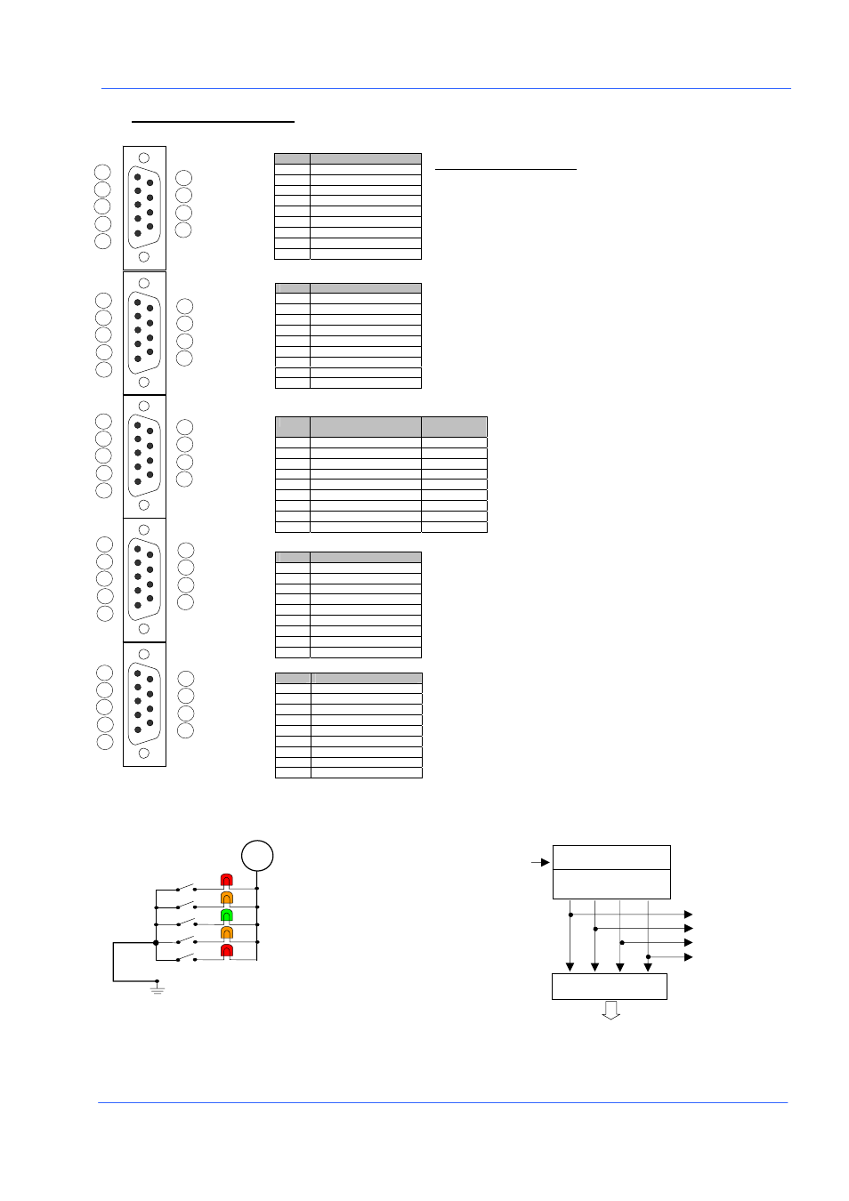
3.1 LAYOUT OF IN/OUTPUT
Circuit connection diagram (OUTPUT)
CH-Bus diagram
Pin#
Functions
1
* (not connected)
2 Rxd
3 Txd
4 Vcc
5 Gnd
6
* (not connected)
7 Rts
8 Cts
9 Gnd
Pin#
Functions
1
RS 232 sortie (0.5 sec.)
2
Current value display
3 Dynamic/Static
4 M1->M2->M3->M4
5 Hold
measure
6
* (not connected)
7
* (not connected)
8
* (not connected)
9 Gnd
Pin#
Functions
Class Mode
(Binary)
1
O.K (Green)
Bit 0
2
* (not connected)
Bit 1
3
Approch + (Orange)
Bit 2
4
+N.G (Red)
Bit 3
5
* (not connected)
Bit 4
6
Approch – (Orange)
Bit 5
7
-N.G (Red)
Bit 6
8
Drive Voltage
9 Gnd
Pin#
Functions
1 D/A
sortie
2
* (not connected)
3
* (not connected)
4
* (not connected)
5
* (not connected)
6
* (not connected)
7
* (not connected)
8
* (not connected)
9 Gnd
Pin#
Functions
1 Ex-A
2 Ex-B
3 Ex-C
4 Ex-D
5 Gnd
6
* (not connected)
7
* (not connected)
8
* (not connected)
9 Gnd
1
2
3
4
5
6
7
8
9
1
2
3
4
5
6
7
8
9
1
2
3
4
5
6
7
8
9
1
2
3
4
5
6
7
8
9
1
2
3
4
5
6
7
8
9
RS-232 C
EXT.CON
OUTPUT
DC OUT
CH-BUS
Analog board PCB
A B C D
A/E
-Converter
Display controller
EX-A (pin #1)
EX-B (pin #2)
EX-C (pin #3)
EX-D (pin #4)
Probe
input
(Connection of a serial printer or a PC)
In the case of RS232-RS mode is set as “PRINT”, the display value is printed via the RS232 by
connecting the pins #1,9 of external control..
If the RS 232-RS mode is set as « HOST », the communication becomes (duplex) and allows to
use the communicator software.
The external control functions can be activated by connecting the pins #1 to 5 to the pin
#9(GND) according to the required function.
The following functions can be activated by connecting the pin #9 to pin # (foot pedal, box)
#1)Print the display value. #2) Change dynamic mode to static mode
#3) Reset the dynamic mode (min., max.) #4) Move the measurement mode (M1) to M2,……
M2,M3,M4 should be active. (ON)
#5) Freeze the displayed value.
Active the preset mode by connecting the pin #3 and #5 simultaneously
Active the contact with GND pin#9 when the value of the bar is positioned in the
corresponding range pins #1, 3, 4, 6, 7) .
This application shows if the product is acceptable or not with an external unit
such as lamps, relays, by powering the pins #8,9.
If the Class mode is turned on, the judgement mode(OK, +/-NG, etc.) is
automatically turned off and the data is output with BCD code through the same
port(each pin).(Refer to the chapter 3.6 for setting up.)
Analog output of the display (Signal Voltage (pin #1 and #9).
The voltage range is : Approx. ±4.3V with ±1 mm, or ±0.05 inch
This function is used when the signal of a probe should be shifted to a second column.
Application : Example : Display a maximum value on 1 column and a minimum value to the other
column with only one probe..
The analog board of the column which is receiving the data should be disconnected,
.
Red
(bigger value than TOLER+)
Green
(Value between APPRO- and APPRO+)
Orange
(Value between APPRO- and TOLER-)
Red
(smaller value than TOLER-)
E=External voltage
Orange
(Value between APPRO+ and TOLER+)
GND
E
#7
#4
#6
#3
#1
#9