7 reinstalling the cover on the vsm500 unit – Rockwell Automation VSM500 Integrated Drive/Motor DeviceNet Option Board User Manual
Page 19
Installing the DeviceNet Option Board
2-5
2.6
Connecting the DeviceNet Option Board and VSM500
Unit to the Network
Step 1. Verify that power has been removed from the VSM500 unit and network.
Step 2. Connect a DeviceNet cable to the network.
Important: Maximum cable length depends on data rate. Refer to the DeviceNet
Cable System Planning and Installation Manual.
Step 3. Connect a Linear plug to the DeviceNet cable.
Step 4. Connect the DeviceNet cable to the VSM500 unit. Figure 2.5 shows an
example.
2.7
Reinstalling the Cover on the VSM500 Unit
Step 1. Connect the display cable and install the cover (see figure 2.5).
Step 2. Tighten the screws on the cover to 1.46 Nm (13 in-lb).
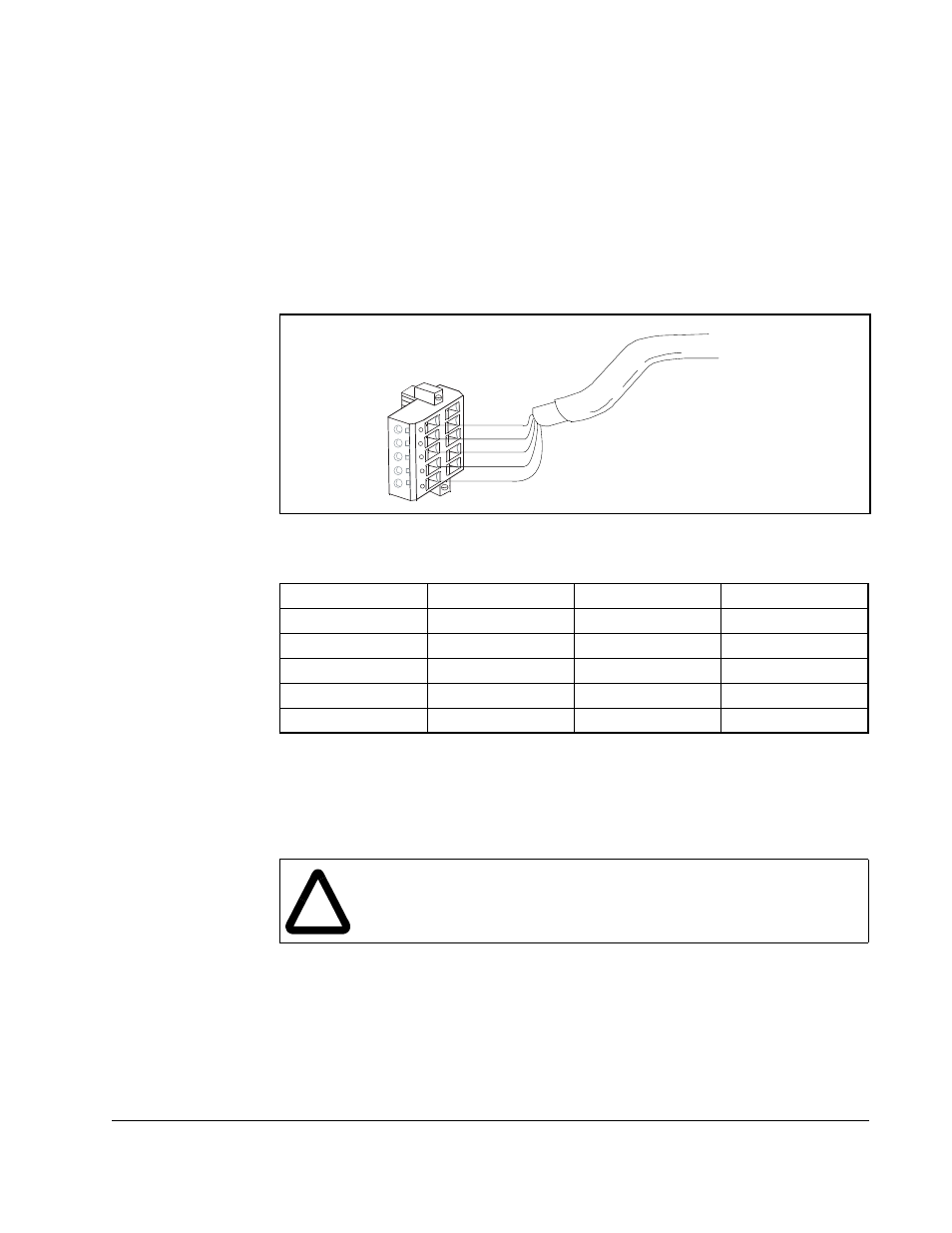
Figure 2.4 – Connecting a 10-Pin Linear Plug to the Cable
Table 2.4 – Linear Plug Terminal Connections
Terminal
Color
Signal
Function
5
Red
VDC+
Power Supply
4
White
CAN_H
Signal High
3
Bare
SHIELD
Shield
2
Blue
CAN_L
Signal Low
1
Black
COMM
Common
5
4
3
2
1
Red
White
Bare
Blue
Black
!
ATTENTION: The cover screws must be securely tightened in order to
properly ground the cover. Verify that all four cover screws are tightened
to 1.46 Nm (13 in-lb) before applying power to the VSM500 unit. Failure
to obsere this precaution could result in severe bodily injury or loss of life.