1 setting the fault configuration parameters – Rockwell Automation MD65 EtherNet/IP Communication Module User Manual
Page 32
4-10
EtherNet/IP Communications Module
Changes to these parameters take effect immediately. A reset is not
required.
4.7.1 Setting the Fault Configuration Parameters
If you set parameter 18 (Comm Flt Action) or parameter 19 (Idle Flt
Action) to “Send Flt Cfg,” the values in the parameters shown in
table 4.5 are sent to the drive after a communications fault and/or
idle fault occurs. You must set these parameters to values required
by your application.
Changes to these parameters take effect immediately. A reset is not
required.
Table 4.4 – Selections for Drive Response to Communication Fault
Value
Action
Description
0
Fault (default)
The drive is faulted and stopped (Default).
1
Stop
The drive is stopped, but not faulted.
2
Zero Data
The drive is sent 0 for output data after a
communications disruption. This does not
command a stop.
3
Hold Last
The drive continues in its present state after a
communications disruption.
4
Send Flt Cfg
The drive is sent the data that you set in the
fault configuration parameters, Flt Cfg Logic
(20) and Flt Cfg Ref (21).
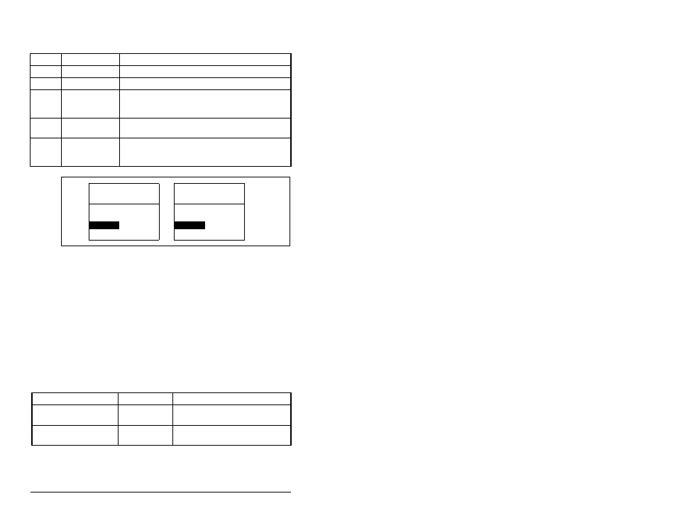
Figure 4.10 – Comm Flt Action Screen and Idle Flt Action Screen on an LCD
OIM
Port 5 Device
MDCOMM-ENET
Parameter #: 18
Comm Flt Action
0
Fault
Port 5 Device
MDCOMM-ENET
Parameter #: 19
Idle Flt Action
0
Fault
Table 4.5 – Fault Configuration Parameters
Parameter Number
Name
Description
20
Flt Cfg Logic
A 16-bit value sent to the drive
for Logic Command.
21
Flt Cfg Ref
A 16-bit value (0 - 65535) sent
to the drive as a Reference.