Rockwell Automation LDC Iron Core Linear Servo Motors User Manual
Page 74
74
Rockwell Automation Publication LDC-UM001B-EN-P - March 2011
Appendix A Specifications and Dimensions
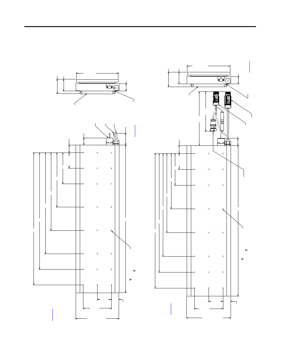
Figure 15 - LDC-Series Iron Core Lin
ear Motor Coil Dim
ensions (LDC-C0150
xxx
-x
HT20) with Flying Leads
Fi
gure 16 - LDC-Series Iron Core Lin
ear
Mo
tor
Co
il Dim
ensio
ns (LDC
-C
150
xxx
-x
HT11)
wi
th Conn
ecto
rs
61.72 ± 0.13
(2.430 ± 0.005)
49.72 ± 0.13
(1.957 ± 0.005)
33.65
(1.325)
66.67
(2.625)
A
B
C
D
E
F
30.00
(1.181)
1000 ± 20
(39.4 ± 0.8)
M5 x 0.8 15 (0.59) total depth,
threads start at 5 (0.20).
S
ee table for hole quantity
.
32.50
(1.280)
L
60.00
(2.362)
120.00
(4.724)
185.00 +1.00
- 0.00
(7.283 +0.039
-0.000)
31.24
(1.230)
180.00
(7.087)
Ref.
See
ta
bl
e o
n
pa
ge
75
fo
r flat
ne
ss o
f
coi
l mo
un
ti
ng
su
rf
ac
e.
Coo
lin
g pla
te
asse
mb
ly sho
w
n
fo
r re
fe
re
nc
e.
Dimensions are in
mm (in
.)
Ma
gn
et
t
ra
ck
shown for
re
fe
re
nc
e.
Hall Effect
Module
Fl
ying L
eads
Th
er
mist
or
Ca
ble
s
Flyi
ng Leads
Mo
to
r Po
we
r
Fl
ying L
eads
Th
es
e d
ime
nsi
on
s a
re
critical to
maintain the
pr
op
er
air ga
p.
Re
fe
r
to
t
he
t
ab
le
on
pa
ge
75
for
le
tte
re
d
di
men
sio
ns.
33.65
(1.325)
66.67
(2.625)
A
B
C
D
E
F
32.50
(1.280)
60.00
(2.362)
120.00
(4.724)
185.00 +1.00
-0.00
(7.283 +0.039
-0.000)
30.00
(1.181)
L
61.72 ± 0.13
(2.430 ± 0.005)
49.72 ± 0.13
(1.957 ± 0.005)
600
(24)
350
(13.9)
180.00
(7.087)
Ref.
31.24
(1.23)
M5 x 0.8 15 (0.59) total depth,
threads start at 5 (0.20).
S
ee table for hole quantity
.
Se
e ta
ble o
n
pa
ge
75
fo
r
fl
at
ne
ss
o
f
coi
l mo
un
ti
ng
su
rf
ac
e.
Fe
ed
ba
ck Co
nn
ecto
r
Ma
gn
et
t
ra
ck
shown for
re
fe
re
nce
.
Co
oli
ng
p
lat
e
assembl
y shown
fo
r ref
er
en
ce
.
En
cod
er
Co
nn
ec
to
r
Po
wer Co
nn
ecto
r
Dimensions are in mm
(in.)
Th
ese
dimen
sio
ns a
re
critical to mai
ntain
th
e pr
op
er
a
ir ga
p.
Re
fer
t
o th
e ta
ble
on
pa
ge
75
fo
r
let
ter
ed