Mounting and wiring two identical coils in tandem, Cables exit to the right – Rockwell Automation LDC Iron Core Linear Servo Motors User Manual
Page 42
42
Rockwell Automation Publication LDC-UM001B-EN-P - March 2011
Chapter 5 Wire the LDC-Series Linear Motor
Mounting and Wiring Two
Identical Coils in Tandem
This type of installation requires a custom motor-database file, which is available
upon request. Contact Application Engineering at 631.344.6600 to request this
file.
These tables and figures show the wiring and spacing for two identical coils
mechanically top mounted to the same plate and driven by one amplifier. There
are three configurations shown here for mounting motors in tandem: power and
encoder cables exiting on the right, the center, and on opposite ends.
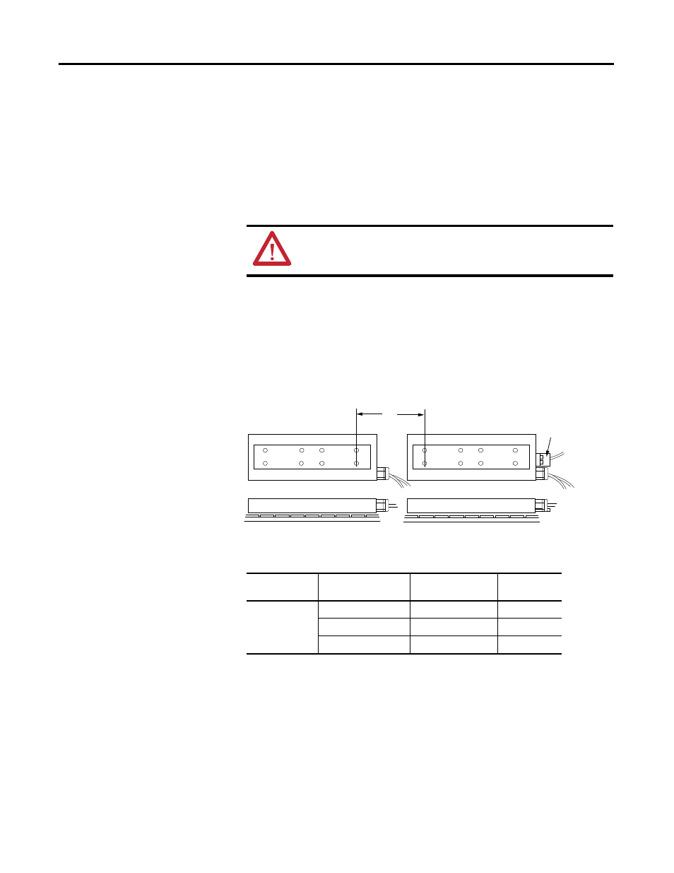
Cables Exit to the Right
If mounting coils in tandem, such that the power cables exit both the coils on
right side, as shown, use the following table to find the mounting distance and the
phase wiring.
Figure 3 - Mounting Two Coils with Cables Exit to the Right
Coils must have identical part numbers. Using mismatched coils
will cause a hazardous condition resulting in damage to the
equipment and a possible fire.
Coil #1
Coil #2
Coil #1 is the master.
Hall Effect
Module
L
Table 5 - Phase Wiring for Right-exit Power Cables
L
mm (in.)
Coil # 1
Master
(1)
Coil # 2
Slave
(2)
Amplifier
Phase
133.33 (5.249)
Red
Red
U
White
White
V
Black
Black
W
(1) Master has Hall effect module.
(2) Slave has no Hall effect module.