Rockwell Automation LDC Iron Core Linear Servo Motors User Manual
Page 67
Rockwell Automation Publication LDC-UM001B-EN-P - March 2011
67
Specifications and Dimensions Appendix A
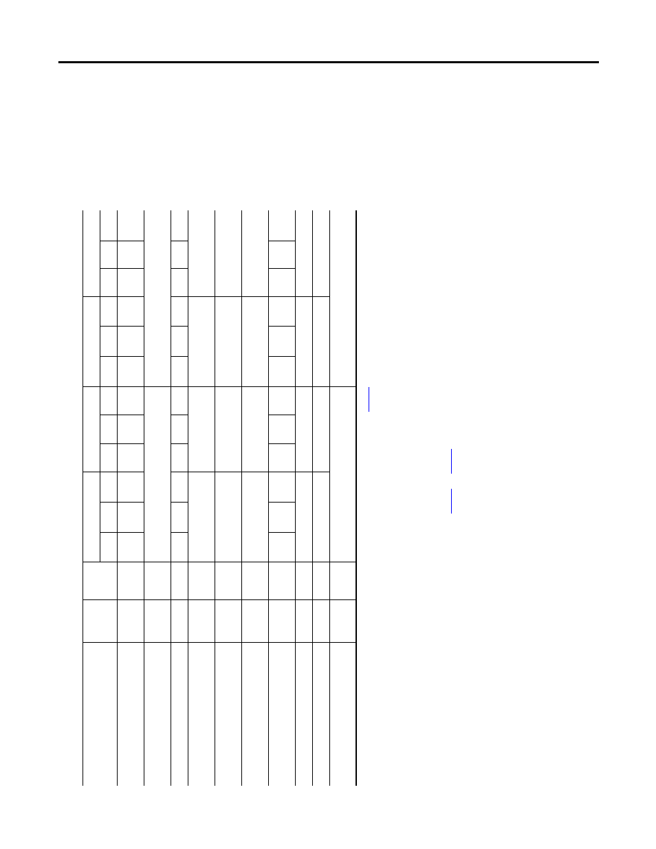
Table 12 - LDC-Series Iron Core Li
near Motors (150 mm
frame size)
A
ttri
bute
U
ni
ts
Symbol
LD
C-C1
50
40
0-D
x
T
xx
LD
C-C1
50
40
0-
E
x
T
xx
LD
C-C
150
60
0-D
x
T
xx
LD
C-C
150
60
0-E
x
T
xx
NC
AC
WC
NC
AC
WC
NC
AC
WC
NC
AC
WC
Fo
rc
e,
co
nt
in
uo
us
(1
)
(2)
(3
)
N
(lbf)
F
c
12
81
(288)
16
01
(360)
19
22
(4
32
)
12
81
(288)
16
01
(3
60
)
19
22
(432)
19
22
(4
32
)
24
02
(540)
28
82
(6
48)
19
22
(4
32
)
24
02
(540)
28
82
(648)
Fo
rce, pe
ak
(4
)
N
(lbf)
F
p
34
98
(786)
52
46
(1
17
9)
Th
erma
l r
esistan
ce
°C/W
R
th
0.
20
0.1
3
0.
09
0.
20
0.
13
0.
09
0.13
0.0
9
0.
06
0.13
0.
09
0.0
6
Fo
rce con
stan
t
(5
)
(6)
(7
)
N/A
pk
(lb
f/A
pk
)
K
f
91
.0
(20.5)
18
2.
0
(40.9)
91
.0
(2
0.
5)
18
2.0
(4
0.
9)
Back
EMF cons
tant p-p
(5
)
(6
)
(7
)
V
p
/m/s
(V
p
/in/s)
K
e
10
7.
5
(2.73)
21
5.
0
(5.46)
10
7.5
(2
.7
3)
21
5.0
(5
.4
6)
Cur
ren
t, pe
ak
(4
)
(6
)
A
pk
(A
rms
)
I
p
45
.2
(32.0)
22
.6
(16.0)
67
.8
(4
7.
9)
33
.9
(2
4.
0)
Cur
ren
t, co
nt
inuo
us
(1
)
(2)
(3
)
(6
)
A
pk
(A
rm
s
)
I
c
14
.1
(10.0)
17
.6
(1
2.4)
21
.1
(1
4.
9)
7.
0
(5.0)
8.8
(6
.2
)
10
.6
(7.5)
21
.1
(1
4.
9)
26
.4
(1
8.
7)
31
.7
(2
2.4)
10
.6
(7
.5
)
13
.2
(9.3)
15
.8
(1
1.
2)
Resist
an
ce
p-
p @ 20
°C
(6
8 °F)
(5
)
(7)
Oh
ms
R
20
2.
12
8.
48
1.
41
5.
65
In
du
ctan
ce p-
p
(5
)
(7
)
mH
L
22
86
14
58
Ma
gn
etic att
ra
ct
io
n
(8
)
N
(lbf)
F
a
78
60
(1
76
8)
11
79
0
(2
65
2)
(1
)
C
oi
ls
at maximu
m tempera
ture,
13
0
°C
(2
66 °F),
mo
unted
to
an
aluminium h
eat sink
wh
ose ar
ea is n
oted
in
tab
le
on
, and at
40
°
C
(1
04 °F) ambient.
(2
)
C
on
tin
uous f
orce a
nd curr
ent
based
on
co
il moving
with
all phases sharing the s
ame
load
in
sinusoidal commutation.
(3
)
For
stan
dstill conditions, multiply
con
tin
uous fo
rc
e an
d cont
inuo
us curren
t by
0.9.
(4
)
C
al
culated
at
20% du
ty cycle
for
1.0 secon
d max. Some
applic
at
ions may
pr
oduce significantly
higher peak forces. Call Applic
ations Engineering (6
31.
344.6600) fo
r de
tails.
(5
)
W
in
ding
pa
rameters listed are
me
asured line-to-
line (ph
ase-to-pha
se
).
(6
)
C
urrents a
nd
vo
ltag
es listed
are
measure
d 0-
peak o
f the
sine
wa
ve
un
less
noted
as
rms.
(7
)
S
pe
cificatio
ns are
±1
0%.
Phase-to-p
hase indu
ct
an
ce is ±
30%.
(8
)
A
ll s
pecificatio
ns
are
at the standa
rd
re
ference air
ga
p
as shown in the drawing on
page
73
and
pag
e
75
.