Rockwell Automation LDC Iron Core Linear Servo Motors User Manual
Page 66
66
Rockwell Automation Publication LDC-UM001B-EN-P - March 2011
Appendix A Specifications and Dimensions
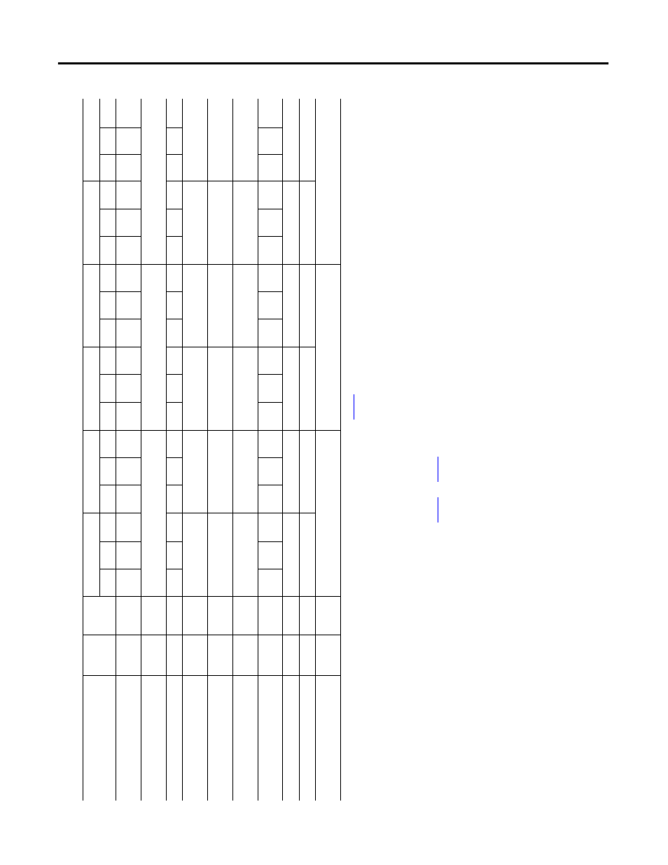
Ta
ble 11 - LDC-Se
rie
s Iro
n
Core
Linea
r Mot
o
rs (
100 m
m
frame
size)
Attribute
U
nits
Symbol
LD
C-C100
300-
D
x
T
xx
LD
C-C10
0300-
E
x
T
xx
LD
C-C1
00400
-D
x
T
xx
LD
C-C
100400
-E
x
T
xx
LDC-
C1006
00-D
x
T
xx
LDC-
C1006
00-E
x
T
xx
NC
AC
WC
NC
AC
WC
NC
AC
WC
NC
AC
WC
NC
AC
WC
NC
AC
WC
Force, continuou
s
(1)
(2)
(3)
N
(lbf)
F
c
674
(152)
843
(190)
1012
(227)
674
(152)
84
3
(190
)
1012
(2
27)
89
9
(202)
112
4
(253)
1349
(30
3)
89
9
(202)
1124
(2
53)
13
49
(303)
1349
(30
3)
1686
(379
)
202
3
(455)
1349
(3
03)
1686
(3
79)
202
3
(455)
Force, pea
k
(4)
N
(lbf)
F
p
1767
(397)
2356
(530)
3534
(79
4)
Therma
l resistan
ce
°C
/W
R
th
0.33
0.21
0.
15
0.33
0.
21
0.15
0.
25
0.16
0.1
1
0.
25
0.16
0.11
0.1
7
0.
11
0.07
0.17
0.11
0.07
Force c
onstant
(5
)
(6
)
(7)
N/
A
pk
(lbf/A
pk
)
K
f
60.7
(13.6
)
182
.0
(40.9)
60
.7
(13.6)
121.3
(27.3)
60.7
(13
.6)
121.3
(2
7.3)
Back
EMF constan
t p-
p
(5)
(6)
(7
)
V
p
/m/
s
(V
p
/i
n/s)
K
e
71.7
(1.
82)
215
.0
(5.
46)
71
.7
(1.82)
143.3
(3.64)
71.7
(1.82)
143.3
(3
.64)
Current, p
eak
(4)
(6)
A
pk
(A
rm
s
)
I
p
34.3
(24.2
)
11.4
(8.
1)
45
.7
(32.3)
22
.8
(16.1)
68.5
(48
.4)
34.3
(2
4.2)
Current, con
tinu
ous
(1)
(2)
(3
)
(6)
A
pk
(A
rms
)
I
c
11.1
(7.
9)
13.9
(9.
8)
16
.7
(11.8)
3.7
(2.
6)
4.
6
(3.3)
5.6
(3
.9)
14
.8
(10.5)
18.5
(13.1)
22.2
(15
.7)
7.
4
(5.2)
9.3
(6
.5)
11
.1
(7.9)
22.2
(15
.7)
27
.8
(19.7)
33.3
(23.6)
11.1
(7
.9)
13.9
(9
.8)
16.7
(11.8)
Resistance p-p @
20 °C (68 °F)
(5)
(7
)
Oh
ms
R
20
2.04
18.36
1.
53
6.
12
1.0
2
4.08
In
ductance p-p
(5
)
(7)
mH
L
20
184
15
61
10
41
Magnetic at
traction
(8)
N
(lbf)
F
a
3930
(883)
5240
(1178
)
7860
(17
67)
(1)
C
oils at
maximum
te
mperature
, 130 °C
(266 °F), mounte
d
to
an alumin
ium heat sin
k whose area is
note
d
in table
on
, and
at 40 °C
(104 °F)
am
bi
en
t.
(2)
C
ontinuou
s force and current based
on coil moving
with
al
l p
hases
sha
ring the same loa
d
in sinusoidal c
ommu
tatio
n.
(3)
For standstill c
onditions,
multiply cont
inuous force and continuous current by
0.
9.
(4)
C
alc
ulate
d
at
20
% duty c
ycle
fo
r
1.0 second max. So
me
ap
plicat
ions may
produ
ce
significantly h
ighe
r pe
ak forces. Call
Applic
at
ion
s Eng
ine
ering
(631.344.660
0) for details.
(5)
W
inding paramete
rs
listed are meas
ured
line
-to-line
(phase-to-p
hase).
(6)
C
urrent
s and voltages listed are me
asured 0-pea
k of the sine wave unless
note
d
as
rms.
(7)
S
pecifications are ±10%. Pha
se
-to-phase inductance is ±30%.
(8)
A
ll
specifications are at the
sta
ndard refere
nce
air gap as
sho
w
n
in the
dr
awin
g
on
pa
ge
73
a
nd
page
75
.