Motor coil dimensions – Rockwell Automation LDC Iron Core Linear Servo Motors User Manual
Page 72
72
Rockwell Automation Publication LDC-UM001B-EN-P - March 2011
Appendix A Specifications and Dimensions
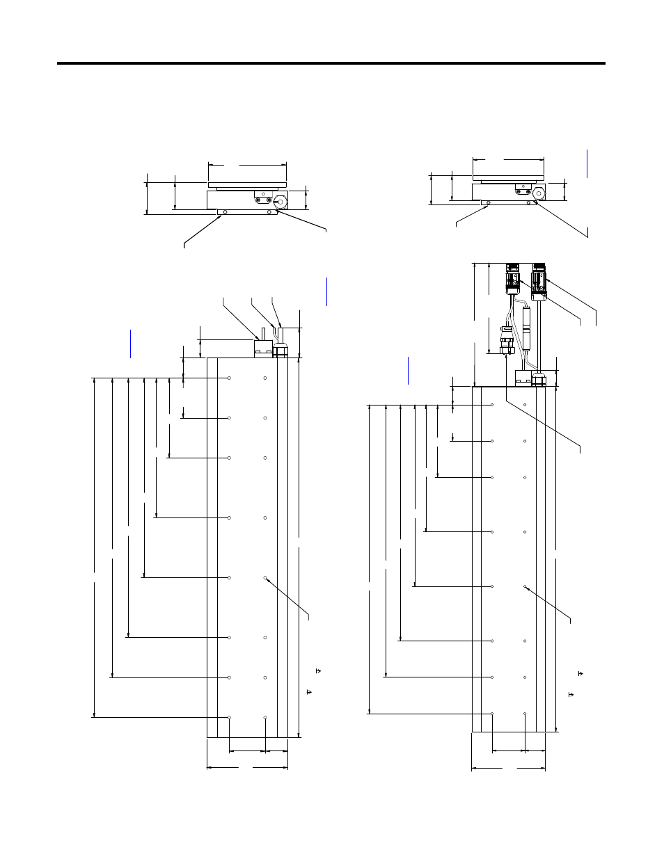
Motor Coil Dimensions
Figure 13 - LDC-Series Iron Core Linear
Motor Coil Dim
ensio
ns (LDC-C030/050/075/100
x
xx-x
HT20) with Flying Leads
Figure 14 - LDC-Series Iron Core Linear
Motor Coil Dim
ensio
ns (LDC-C030/050/075/100
x
xx-x
HT11) w
ith
Co
nnec
tors
45.72 ± 0.13
(1.800 ± 0.005)
30.00
(1.181)
33.65
(1.325)
66.67
(2.625)
53.72 ± 0.13
(2.115 ± 0.005)
31.24
(1.230)
1000 ±20
(39.4 ±0.8)
L
B
C
D
E
F
A
R (ref.)
M
W
H
M5 x 0.8 15 (0.59) total depth,
threads start at 5 (0.20).
S
ee table for hole quantity
.
C
oo
lin
g plat
e
ass
emb
ly
sho
w
n fo
r
re
fe
re
nc
e.
Ha
ll Ef
fe
ct
M
od
ul
e
Fl
yi
ng Leads
Ther
mist
or
Ca
ble
s
Fl
ying L
eads
Mo
to
r Po
wer
Fly
ing Leads
Se
e t
ab
le o
n
pa
ge
73
fo
r
flat
ne
ss
o
f
coi
l mo
un
ti
ng
su
rf
ac
e.
M
agn
et
t
ra
ck
sh
own
for
re
fe
re
nc
e.
Di
men
sio
ns are in mm (in.)
Re
fer
t
o th
e ta
ble
on
pa
ge
73
fo
r
let
ter
ed
Th
es
e dime
ns
ion
s
ar
e critical to
ma
in
ta
in
the
pr
op
er
ai
r ga
p.
33.65
(1.325)
66.67
(2.625)
A
B
C
D
E
F
M
W
H
30.00
(1.181)
L
600
(24)
350
(13.9)
53.72 ± 0.13
(2.115 ± 0.005)
45.72 ± 0.13
(1.800 ± 0.005)
R (ref.)
31.24
(1.230)
M5 x 0.8 15 (0.59) total depth,
threads start at 5 (0.20).
S
ee table for hole quantity
.
See
ta
ble on
pa
ge
73
fo
r fla
tn
ess
of coil moun
ti
ng
su
rf
ac
e.
Fe
ed
ba
ck Con
ne
ctor
M
agn
et
t
ra
ck
sh
own
for
re
fe
re
nc
e.
Co
oling
plat
e
ass
emb
ly
sho
w
n fo
r
re
fe
re
nce
.
Po
wer
Co
nn
ec
to
r
En
cod
er
Co
nn
ect
or
Dimensions are in
mm (in
.)
Th
es
e d
ime
nsi
on
s
are critical to
ma
in
ta
in th
e pr
op
er
ai
r ga
p.
Re
fe
r
to
t
he
t
ab
le
on
pa
ge
73
fo
r
le
tt
er
ed