Rockwell Automation LDC Iron Core Linear Servo Motors User Manual
Page 64
64
Rockwell Automation Publication LDC-UM001B-EN-P - March 2011
Appendix A Specifications and Dimensions
Ta
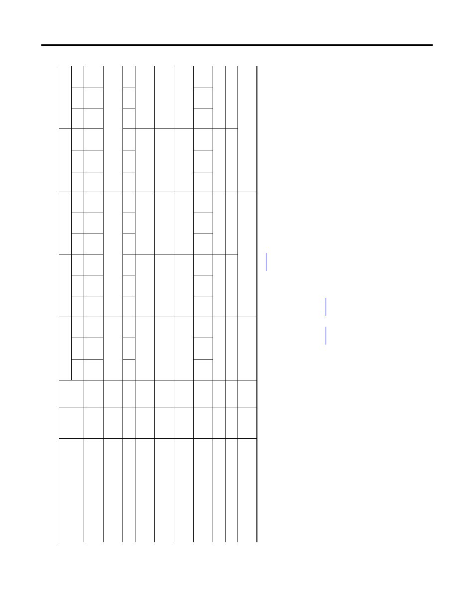
ble 9 - LDC-Se
rie
s Iro
n
Core
Linear Motors (50 mm frame size)
Attribute
U
nits
Sym
bol
LD
C-C
050
10
0-D
x
T
xx
LD
C-C
050
20
0-D
x
T
xx
LD
C-C
050
20
0-E
x
T
xx
LD
C-C0
50
30
0-D
x
T
xx
LD
C-C0
50
30
0-E
x
T
xx
NC
AC
WC
NC
AC
WC
NC
AC
WC
NC
AC
WC
N
C
AC
WC
For
ce
, co
ntin
uo
us
(1
)
(2
)
(3)
N
(lb
f)
F
c
11
9
(2
7)
14
9
(3
4)
17
9
(4
0)
24
0
(5
4)
29
9
(6
7)
35
9
(8
1)
24
0
(5
4)
29
9
(67)
35
9
(8
1)
36
3
(82)
45
3
(102)
54
4
(122)
36
3
(82)
45
3
(102)
54
4
(122)
Fo
rc
e, pe
ak
(4)
N
(lb
f)
F
p
30
2
(6
8)
60
0
(1
35
)
94
1
(212)
Th
er
mal
r
esi
st
an
ce
°C/W
R
th
1.44
0.92
0.64
0.71
0.46
0.
32
0.
71
0.
46
0.
32
0.
48
0.
31
0.
21
0.4
8
0.3
1
0.
21
For
ce
co
nsta
nt
(5
)
(6
)
(7)
N/A
pk
(lbf/A
pk
)
K
f
30
.3
(6
.8
)
30
.3
(6
.8
)
60
.7
(1
3.
6)
30
.8
(6.9)
92
.4
(2
0.8)
Ba
ck EM
F
co
nsta
nt p
-p
(5)
(6
)
(7
)
V
p
/m/s
(V
p
/in/s)
K
e
35
.8
(0
.9
1)
35
.8
(0
.9
1)
71
.7
(1
.8
2)
36
.4
(0.92)
10
9.1
(2.
77)
Cur
re
nt
, pe
ak
(4
)
(6
)
A
pk
(A
rms
)
I
p
11
.7
(8
.3
)
23
.3
(1
6.
5)
11
.6
(8
.2
)
35
.9
(25.4)
12
.0
(8.
5)
Cu
rre
nt
, con
tin
uo
us
(1
)
(2
)
(3
)
(6
)
A
pk
(A
rms
)
I
c
3.9
(2
.8
)
4.9
(3
.5
)
5.9
(4
.2
)
7.9
(5
.6
)
9.9
(7
.0
)
11
.8
(8
.4
)
3.9
(2
.8
)
4.
9
(3.5)
5.9
(4
.2
)
11
.8
(8.3)
14
.7
(1
0.
4)
17
.7
(12.5)
3.9
(2.
8)
4.9
(3.
5)
5.
9
(4.2)
Res
ist
an
ce
p-
p
@ 20
°C (6
8
°F)
(5
)
(7
)
Oh
ms
R
20
3.76
1.88
7.52
1.
25
11
.2
8
In
du
ct
an
ce p-
p
(5)
(7
)
m
H
L
361
87
2
12
10
8
Ma
gn
et
ic
at
tr
ac
ti
on
(8
)
N
(lb
f)
F
a
69
0
(1
55
)
13
79
(3
10
)
20
69
(465)
(1)
C
oils at
maximum
te
mperature
, 130 °C
(266 °F), mounted
to an alumin
ium heat sin
k whose area is noted
in table
on
, and at 40 °C
(104 °F)
amb
ient
.
(2)
C
ontinuous force and current based on coil moving
with
al
l p
hases
shar
ing the same loa
d
in sinusoidal c
ommut
atio
n.
(3)
For
standstill con
ditions, multiply
continuous force and continuous c
urrent by
0.9.
(4)
C
alc
ulate
d
at
20% duty c
ycle
fo
r
1.0 second max. So
me
ap
plicat
ions may
produ
ce
signif
icantly h
ighe
r pe
ak forces. Call
Applic
at
ion
s Eng
inee
ring
(631.344.6600
) for details.
(5)
W
inding parameter
s listed are meas
ured
line
-to-line
(phase-to-p
hase).
(6)
C
urrents and voltages listed are me
asured 0-peak of the sine wave unless
note
d
as
rms.
(7)
S
pecifications are ±10%. Phas
e-
to-phase in
ductance is ±30%.
(8)
A
ll specifications are at
the
stan
dard re
feren
ce
air
gap
as shown
in t
he d
rawing
on
pag
e
73
a
nd
page
75
.