Understanding rbm connectors – Rockwell Automation 2090-XBxxx Resistive Brake Module Installation Instructions User Manual
Page 9
Publication 2090-IN009F-EN-P — November 2004
Resistive Brake Module Installation Instructions
9
Ensure all fasteners are properly bonded to the subpanel. Refer to the
System Design for Control of Electrical Noise Reference Manual (publication
GMC-RM001x-EN-P) for HF bonding techniques.
3. Tighten all mounting fasteners. The minimum recommended torque for
M6 (1/4 in. - 20) bolts is 1 Nm (9 in-lb).
Understanding RBM
Connectors
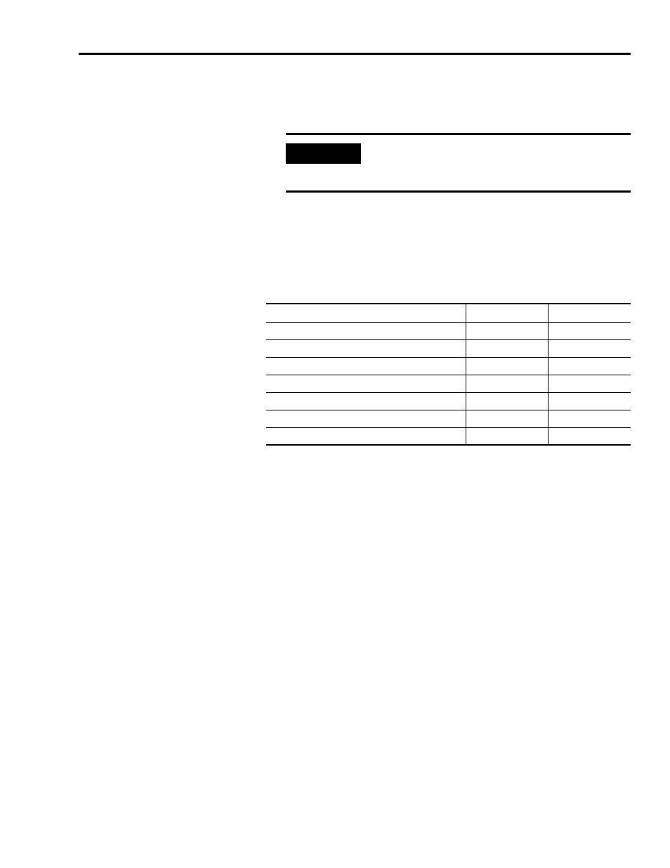
RBMs have connectors and status indicators as listed in the following table:
• Connectors and indicators locations are shown in Figure 6 on page 10 for
the 2090-XB33-xx, and Figure 7 on page 10 for the 2090-XB120-xx.
• Block diagrams of electrical functions are provided as Figure 8 on page 11
for the 2090-XB33-xx, and Figure 9 on page 12 for the 2090-XB120-xx.
• Connector functions for the 2090-XB33-xx, and the 2090-XB120-xx are
described in RBM Wiring Requirements on page 13.
IMPORTANT
To improve the bond between the RBM and subpanel,
construct your subpanel out of zinc plated (paint-free)
steel.
RBM Connectors or Indicators
2090-XB33-xx
2090-XB120-xx
X
X
X
X
X
X
TB4 - 230VAC Aux Power Connection
–
X
X
–
–
X
–
X